
Electric Company Computer Drive User Manual


www.supportme.net
Basic Installation 3-5MN1942
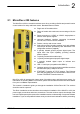
3.2.2 Mounting and cooling the MicroFlex e100
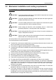
Ensure you have read and understood the Mechanical installation and location requirements in
section 3.2. Mount the MicroFlex e100 vertically on its rear side, the side opposite the front panel.
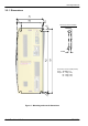
M5 bolts or screws should be used to mount the MicroFlex e100. Detailed dimensions are shown
in section 3.2.1.
For effective cooling, the MicroFlex e100 must be mounted upright on a smooth vertical metal
surface. The MicroFlex e100 is designed to operate in an ambient temperature of 0°C to 45°C
(32°F to 113°F). Output current must be derated between 45°C (113°F) and the absolute
maximum ambient temperature of 55°C (131°F). Within the ambient temperature range:
The 3A model is designed to operate without any additional cooling methods.
The 6A and 9A models require a forced air flow, passing vertically from the bottom to the top of
the MicroFlex e100 case, to allow full rated current at 45°C (113°F).
Temperature derating characteristics are shown in sections 3.2.3 to 3.2.5.
Note: Failure to meet cooling air flow requirements will result in reduced product lifetime
and/or drive overtemperature trips. It is recommended to check periodically the
operation of the cooling equipment. Optional fan tray F AN001-024, mounted exactly
as shown in section A.1.1., ensures that correct cooling is provided and allows the
MicroFlex e100 to be UL listed.
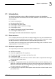
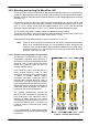
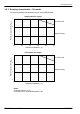
3.2.2.1 Effects of mounting surface and proximity
The proximity of the MicroFlex e100 to other
components could affect cooling efficiency. If
the MicroFlex e100 is mounted beside another
MicroFlex e100 (or other obstruction), there
should be a minimum space of 15mm to
maintain effective cooling.
If the MicroFlex e100 is mounted above or
below another MicroFlex e100 (or other
obstruction), there should be a minimum space
of 90mm to maintain effective cooling.
Remember that when a MicroFlex e100 is
mounted above another MicroFlex e100 or
heat source, it will be receiving air that has
been already heated by the device(s) below it.
Multiple MicroFlex e100 units mounted above
each other should be aligned, not offset, to
promote air flow across the heatsinks.
The derating characteristics assume the
MicroFlex e100 is mounted on 3mm thick (or
less) metal plate. If the MicroFlex e100 is
mounted on 10mm plate then the current
characteristics shown in sections 3.2.3 to 3.2.5
may be increased by up to 7% if there is no
forced air cooling, or 15% if forced air cooling
is present.
It is recommended to allow approximately
60mm at the front to accommodate wiring and
connectors.
Forced air flow
Fan Fan
15mm
15mm
90mm
Figure 2 - Cooling and proximity
Metal backplane
Cool Warm Hot