
Electric Company Computer Drive User Manual


www.supportme.net
Basic Installation 3-1MN1942
3.1 Introduction
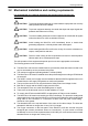
You should read all the sections in Basic Installation to ensure safe installation.
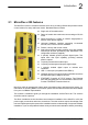
This section describes the mechanical and electrical installation of the MicroFlex e100 in the
following stages:
H Location considerations
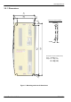
H Mounting the MicroFlex e100
H Connecting the AC power supply
H Connecting the 24VDC control circuit supply
H Connecting the motor
H Installing a regeneration resistor (Dynamic Brake)
H Connecting the feedback device
These stage s should be read and followed in sequence.
3.1.1 Power sources
A 115 - 230V AC power source (IEC1010 over-voltage category III or less) in the installation area
is required. This may be single-phase or three-phase. An AC power filter is required to comply
with the CE directive for which the MicroFlex e100 was tested (see section 3.4.7).
The 24VDC control circuit supply must be a regulated power supply with a continuous current
supply capability of 1A (4A power on surge).
3.1.2 Hardware requirements
The components you will need to complete the basic installation are:
H 24VDC power supply.
H AC power supply filter (for CE compliance).
H The motor that will be connected to the MicroFlex e100.
H A motor power cable.
H An encoder feedback cable, SSI cable, or EnDat / SinCos cable. A separate Hall cable might
also be required for linear motors.
H A USB cable.
H (Optional) A regeneration resistor (Dynamic Brake) might be required, depending on the
application. Without the regeneration resistor , the drive may produce an overvoltage fault. All
MicroFlex e100 models have overvoltage sensing circuitry. Regeneration resistors may be
purchased separately - see Appendix A.
H A cooling fan may be required to allow operation of the MicroFlex e100 at full rated current
(see section 3.2.2).
3 Basic Installation
3