Resolver to Digital Expansion Board Catalog No.
Table of Contents Section 1 General Information . . . . . . . . . . . . . . . . . . . . . . . . . . . . . Introduction . . . . . . . . . . . . . . . . . . . . . . . . . . . . . . . . . . . . Limited Warranty . . . . . . . . . . . . . . . . . . . . . . . . . . . . . . . Safety Notice . . . . . . . . . . . . . . . . . . . . . . . . . . . . . . . . . . Precautions . . . . . . . . . . . . . . . . . . . . . . . . . . . . . . . . . Section 2 Expansion Board Description . . . . . . . . . . . . . . . . . . . .
Section 4 Hardware Setup . . . . . . . . . . . . . . . . . . . . . . . . . . . . . . . . . Connections . . . . . . . . . . . . . . . . . . . . . . . . . . . . . . . . . . . Section 5 Software Setup . . . . . . . . . . . . . . . . . . . . . . . . . . . . . . . . . . Configure Control Software . . . . . . . . . . . . . . . . . . . . . . Series 18H and 22H Vector Controls . . . . . . . . . . . . Series 19H and 20H DC SCR Controls . . . . . . . . . .
Section 1 General Information Introduction The Baldor controls represent the latest technology in microprocessor based motor controls. In addition to the user programmable parameters available in every control, many different expansion boards are available from Baldor to further customize the control to most any application. Expansion boards are categorized by compatibility into two groups: Group 1 and Group 2, see Table 1-1. A board from either group may be used alone in a control.
Limited Warranty For a period of two (2) years from the date of original purchase, BALDOR will repair or replace without charge controls and accessories which our examination proves to be defective in material or workmanship. This warranty is valid if the unit has not been tampered with by unauthorized persons, misused, abused, or improperly installed and has been used in accordance with the instructions and/or ratings supplied.
Safety Notice This equipment contains voltages that may be as great as 1000 volts! Electrical shock can cause serious or fatal injury. Only qualified personnel should attempt the start-up procedure or troubleshoot this equipment. This equipment may be connected to other machines that have rotating parts or parts that are driven by this equipment. Improper use can cause serious or fatal injury. Only qualified personnel should attempt the start-up procedure or troubleshoot this equipment.
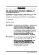
WARNING: Be sure the system is properly grounded before applying power. Do not apply AC power before you ensure that all grounding instructions have been followed. Electrical shock can cause serious or fatal injury. WARNING: Do not remove cover for at least five (5) minutes after AC power is disconnected to allow capacitors to discharge. Dangerous voltages are present inside the equipment. Electrical shock can cause serious or fatal injury.
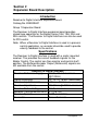
Section 2 Expansion Board Description Introduction Resolver to Digital Interface Expansion Board Catalog No. EXB009A01 Group 1 Expansion Board The Resolver to Digital Interface expansion board provides closed loop operation for the Baldor Series 18H, 19H, 20H and 22H controls. The Resolver to Digital Interface can also be used for PID control. Note: When a Resolver to Digital Interface is used in a process control application, an encoder should be used to provide velocity feedback to the control.
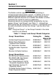
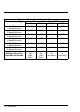
Maximum Motor Speed / Resolver Speed Resolver Speed p Type yp Maximum Motor Speed (RPM) 10 Bits 12 Bits 14 Bits 16 Bits (2 Pole) 62,400 15,600 3,900 975 1 Speed Resolver (4 Pole) 31,200 7,800 1,950 487 2 Speed Resolver (6 Pole) 20,800 5,200 1,300 325 3 Speed Resolver (8 Pole) 15,600 3,900 975 244 4 Speed Resolver (10 Pole) 12,480 3,120 780 195 5 Speed Resolver (12 Pole) 10,400 2,600 650 163 6 Speed Resolver Maximum Resolver Speed/Bit Resolution 2-2 Description 128 (256 Poles) 64 (128 Poles) 32 (64 Poles
Section 3 Installation Board Installation This section describes the Expansion Board installation procedure. Caution: Before you proceed, be sure to read and become familiar with the safety precautions at the beginning of this manual. Do not proceed if you are unsure of the safety precautions described. If you have any questions, contact BALDOR before you proceed. 1. Remove the expansion board from the shipping container. 2. Remove all packing material from the board.
1-15HP Size A and B Controls (For all 15H Inverter, 18H Vector, and 23H Servo). Single Expansion Board Installation Procedure: 1. Be sure drive operation is terminated and secured. 2. Remove all power sources from the control. 3. Wait at least 5 minutes for internal capacitors to discharge. 4. Remove the four (4) Phillips head screws that secure the control cover. 5. Remove the control cover. 6. Remove the #6 screw at position MH1 (upper left on the main circuit board. See Figure 3-1. 7.
Figure 3-1 Single Expansion Board Installation Expansion Board Remove screw (Labeled MH1 in Main PCB Screen). Install Male/Female Standoff. Main Control Board Install Female/Female Aluminum Standoff. Install Female/Female Nylon Standoff. Terminal tightening torque is 7 lb-in (0.8 Nm) maximum. Figure 3-2 Single Expansion Board Installation #6 Screw Group 1 or 2 Expansion Board Long Aluminum or Nylon Standoff Female/Female shown. Use Male/Female in place of (MH1) screw Figure 3-1.
1-15HP Size A and B Controls (Continued) Dual Expansion Board Installation Procedure: 1. Be sure drive operation is terminated and secured. 2. Remove all power sources from the control. 3. Wait at least 5 minutes for internal capacitors to discharge. 4. Remove the four (4) Phillips head screws that secure the control cover. 5. Remove the control cover. 6. Remove the #6 screw at position MH1 (upper left on the main circuit board. See Figure 3-1. 7.
1-15HP Size A and B Controls Dual Expansion Board Installation (Continued) 13. The mechanical installation of the first expansion board is now complete. Refer to the manual for the Group 2 board and configure any jumpers and switches as desired. Also complete the wiring for this board before you install the cover. 14. When complete, install the control cover using the four (4) Phillips head screws. 15. Restore all power sources to the control. 16. Restore drive operation.
HP Size C and Larger AC Controls (For all 15H Inverter, 21H Line Regen Inverter, 18H Vector, 22H Line Regen Vector and 23H Servo). Single Expansion Board Installation Procedure: 1. Be sure drive operation is terminated and secured. 2. Remove all power sources from the control. 3. Wait at least 5 minutes for internal capacitors to discharge. 4. Remove the four (4) Phillips head screws (1/4 turn) that secure the control cover. (On floor mounted G size enclosures, open the enclosure door). 5.
15HP Size C and Larger AC Controls Single Expansion Board Installation (Continued) Figure 3-4 Single Expansion Board Installation Expansion Board Motor Control Board Terminal tightening torque is 7 lb-in (0.8 Nm) maximum.
15HP Size C and Larger AC Controls (Continued) Dual Expansion Board Installation Procedure: 1. Be sure drive operation is terminated and secured. 2. Remove all power sources from the control. 3. Wait at least 5 minutes for internal capacitors to discharge. 4. Remove the four (4) Phillips head screws (1/4 turn) that secure the control cover. (On floor mounted G size enclosures, open the enclosure door). 5. Remove the control cover. 6.
15HP Size C and Larger AC Controls Dual Expansion Board Installation (Continued) 12. When complete, install the control cover using the four (4) Phillips head screws (1/4 turn). (On floor mounted G size enclosures, close the enclosure door). 13. Restore all power sources to the control. 14. Restore drive operation.
SCR DC Controls (For 19H and 20H SCR DC Controls). Single Expansion Board Installation Procedure: 1. Be sure drive operation is terminated and secured. 2. Remove all power sources from the control. 3. Wait at least 5 minutes for internal capacitors to discharge. 4. Slide the expansion board male connector into the female connector of the control board. See Figure 3-4. 5. Securely mount the expansion board to the sheet metal mounting plate using the #6 screws provided in the installation hardware.
SCR DC Controls (Continued) Dual Expansion Board Installation Procedure: 1. Be sure drive operation is terminated and secured. 2. Remove all power sources from the control. 3. Wait at least 5 minutes for internal capacitors to discharge. 4. Slide the Group 1 board male connector into the female connector of the control board. See Figure 3-4. 5. Securely mount the Group 1 expansion board to the sheet metal mounting plate using the short standoffs provided in the installation hardware. See Figure 3-6. 6.
3-12 Installation
Section 4 Hardware Setup Important: If the Resolver to Digital expansion board is installed in a Vector control that has a feedback module installed, the feedback module must be removed to prevent interference with the expansion board. Figure 4-1 shows how to identify the feedback module on the DSP Main Control Board. The main control board is where the keypad plugs in.
If your Vector control does not look like the one pictured in Figure 4-1, do not perform the feedback module removal procedure. Instead, continue onto page 4-3. Feedback Module Removal Procedure If your Vector control looks like the one pictured in Figure 4-1, perform the following procedure: The resolver feedback module must be removed from the main control board to change the JP1 position. Use the following procedure. 1. 2. Be sure drive operation is terminated and secured.
Connections WARNING: High voltage is present on the Resolver to Digital expansion board. Do not touch any circuit board, power device or electrical connection before you first ensure that power has been disconnected and there is no high voltage present from this equipment or other equipment to which it is connected. Electrical shock can cause serious or fatal injury. Only qualified personnel should attempt the start-up procedure or troubleshoot this equipment. Procedure: (Refer to Figure 4-1 and FIgure 4-2.
Figure 4-1 Switch and Terminal Locations DIP Switch OFF 1 All switches shown in OFF position. 2 3 4 5 ON Side View 51 52 53 54 55 56 J1 Terminal tightening torque is 7 lb-in (0.8 Nm) maximum.
Figure 4-2 Resolver Connections R2 S2 R1 S4 P P S3 S1 P 51 SINE+ 52 SINE– 53 COS+ 54 COS– 55 REF+ 56 REF– (Common/ Shield) P = Twisted Pair Terminal tightening torque is 7 lb-in (0.8 Nm) maximum.
4-6 Setup
Section 5 Software Setup Configure Control Software After the Resolver to Digital Interface board has been installed and the DIP switches are correctly set, the control software must be configured. Series 18H and 22H Vector Controls Note: When the Resolver to Digital Interface board is installed, the encoder inputs to the control are automatically disabled (J1 pins 23 to 30). The value of the Level 2, MOTOR DATA Block, “Resolver Speed” parameter (P2509) must be set to the correct speed value. Procedure: 1.
5-2 Software
BALDOR ELECTRIC COMPANY P.O.