
User manual

Copyright © 2000 EIM Company, Inc 13840 Pike Road Missouri City, TX 77489 (281) 499-1561 Page 3
Controlinc Digital Futronic VIII User Manual
Model DF320A Version 1.0
(
2003-01-31
)
1.3. Theory of Operation
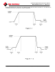
1.3.1. Programmable Speed and Accel/Decel Rates
The EIM Futronic VIII system uses only two speeds, normal and slow. The speeds are programmable
at the VFC. Normal speed is typically set as the standard full speed of the motor at 50 or 60 Hz but may
be set at some other frequency. Selection of the two speeds is dependent on the application
requirements. The system has two independently programmable acceleration rates. One is from stop to
slow speed and the other is from slow speed to normal speed. The system also has two independently
programmable deceleration rates. One is from normal speed to slow speed and the other is from slow
speed to a minimum frequency at which time electric motor brake may be applied. (See Figures 1-1
and 1-2)
1.3.2. Brakes
Much of the required braking is applied to the motor by the VFC absorbing regenerated energy from the
motor during deceleration. Brakes to stop the motor more quickly or under higher load conditions can
be in the form of a DC injection brake or a dynamic brake. The type of braking to use is dependent on
the application. Selection of the type of brakes is programmable at the VFC. DC injection brake
operates by applying the high frequency signal to the motor in only one polarity. Dynamic brakes
operate by dumping excessive regenerated energy from the motor into a resistive load, e.g. a bank of
high power rated resistors. If dynamic brakes are required, some VFCs require an external braking unit
to be added to the system.
1.3.3. Position Control
Precision position control is provided by the DCM320A. This module has a sensitivity of +
0.1%.
Precision of control is adjustable by setting the Position Control bandwidth in the DCM320A. The
DCM320A can provide control precision of ±.25% or better in most applications. When used in
conjunction with the VFC, the system has a repeatability of 0.1% or better in most applications. The
DCM320A has an adjustment for modulation delay time. This provides a delay from the last time the
valve moved to the next time it is allowed to move, preventing valve plugging. This time is normally set
to zero in high-speed modulating applications. The DCM320A also has zero and span calibration
adjustments for the 4-20mA feedback signal. DCM320A setup can be done with EIM Controls CCU
software, or with DIP switches. For DIP switch configuration refer to the Controlinc Quick Startup
Guide.
The DCM320A module provides Open and Close outputs to motor controller VFC to control position of
actuator or valve to within the adjusted control bandwidth. This is accomplished by comparing valve
position feedback signal with position command (setpoint) signal. If a difference between the two
signals is greater than bandwidth setting, an Open or Close digital output is generated. Open or Close
direction is determined by the difference between the two signals being either positive or negative. The
two digital outputs for Open and Close are fed to the VFC interface circuitry, providing isolation and
proper electrical interface to the VFC.