
Specification Sheet

2−4 Installation & Operation MN408
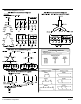
Conduit Box For ease of making connections, an oversize conduit box is provided. Most conduit boxes can be
rotated 360 in 90 increments. Auxiliary conduit boxes are provided on some motors for accessories
such as space heaters, RTD’s etc.
AC Power Motors with flying lead construction must be properly terminated and insulated.
Connect the motor leads as shown on the connection diagram located on the name plate or inside the
cover on the conduit box. Be sure the following guidelines are met:
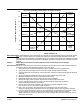
1. AC power is within 10% of rated voltage with rated frequency. (See motor name plate for ratings).
OR
2. AC power is within 5% of rated frequency with rated voltage.
OR
3. A combined variation in voltage and frequency of 10% (sum of absolute values) of rated values,
provided the frequency variation does not exceed 5% of rated frequency.
Performance within these voltage and frequency variations are shown in Figure 2-4.
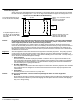
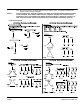
Figure 2-3 Accessory Connections
One heater is installed in each end of motor.
Leads for each heater are labeled H1 & H2.
(Like numbers should be tied together).
Three thermistors are installed in windings and tied in series.
Leads are labeled TD1 & TD2.
Winding RTDs are installed in windings (2) per phase.
Each set of leads is labeled
1TD1, 1TD2, 1TD3, 2TD1, 2TD2, 2TD3 etc.
* One bearing RTD is installed in Drive endplate (PUEP), leads
are labeled RTDDE.
* One bearing RTD is installed in Opposite Drive endplate (FREP), leads
are labeled RTDODE.
* Note RTD may have 2−Red/1−White leads; or 2−White/1−Red Lead.
TD1
TD2
Rotation All three phase motors are reversible. To reverse the direction of rotation, disconnect and lock out power
and interchange any two of the three line leads for three phase motors. For single phase motors, check
the connection diagram to determine if the motor is reversible and follow the connection instructions for
lead numbers to be interchanged. Not all single phase motors are reversible.
Adjustable Frequency Power Inverters used to supply adjustable frequency power to induction motors
produce wave forms with lower order harmonics with voltage spikes superimposed. Turn−to−turn,
phase−to−phase, and ground insulation of stator windings are subject to the resulting dielectric stresses.
Suitable precautions should be taken in the design of these drive systems to minimize the magnitude of
these voltage spikes. Consult the drive instructions for maximum acceptable motor lead lengths, and
proper grounding.