
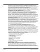
Specification Sheet

2−2 Installation & Operation MN408
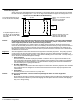
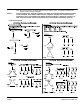
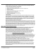
Frame Mounting Holes
Some motors have standardized frames containing 6 or 8 mounting holes. 6 hole frames are not suitable
for field reversal of mounting from F−1 to F−2, etc. Figure 2-2 indicates the proper mounting holes to use.
Figure 2-2 6 & 8 Hole Motor Frame Mounting
Top View
Allows F-1 to F-2 Conversion on 8 hole
frames.
Not present on 6 hole frames.
Not used on 8 hole frames.
Shaft
Always use these holes, closer to the
shaft 112S, 132S, 160M, 180M,
200M, 225S, 250S, 280S, (IEC)
For short frame designations 182, 213,
254, 284, 324, 364, 404, 444 (NEMA)
For long frame designations 184, 215,
256, 286, 326, 365, 405, 445 (NEMA)
(IEC) 112M, 132M, 160L, 200L, 225M,
250M, 280M
Caution: Do not lift the motor and its driven load by the motor lifting hardware. The motor lifting hardware
is adequate for lifting only the motor. Disconnect the load (gears, pumps, compressors, or other
driven equipment) from the motor shaft before lifting the motor.
In the case of assemblies on a common base, any lifting means provided on the motor should not be
used to lift the assembly and base but, rather, the assembly should be lifted by a sling around the base or
by other lifting means provided on the base. Assure lifting in the direction intended in the design of the
lifting means. Likewise, precautions should be taken to prevent hazardous overloads due to deceleration,
acceleration or shock forces.
Alignment
Accurate alignment of the motor with the driven equipment is extremely important. The pulley, sprocket,
or gear used in the drive should be located on the shaft as close to the shaft shoulder as possible. It is
recommended to heat the pulley, sprocket, or gear before installing on the motor shaft. Forcibly driving a
unit on the motor shaft will damage the bearings.
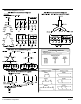
1. Direct Coupling
For direct drive, use flexible couplings if possible. Consult the drive or equipment manufacturer for
more information. Mechanical vibration and roughness during operation may indicate poor alignment.
Use dial indicators to check alignment. The space between coupling hubs should be maintained as
recommended by the coupling manufacturer.
2. End-Play Adjustment
The axial position of the motor frame with respect to its load is also extremely important. The standard
motor bearings are not designed for excessive external axial thrust loads. Improper adjustment will
cause failure.
3. Pulley Ratio
The best practice is to not exceed an 8:1 pulley ratio.
Caution: Do not over tension belts. Excess tension may damage the motor or driven equipment.
4. Belt Drive
Align sheaves carefully to minimize belt wear and axial bearing loads (see End-Play Adjustment). Belt
tension should be sufficient to prevent belt slippage at rated speed and load. However, belt slippage
may occur during starting.