
Specification Sheet

Section 2
Installation & Operation
Installation & Operation 2−1MN408
Overview Installation should conform to the National Electrical Code as well as local codes and practices. When
other devices are coupled to the motor shaft, be sure to install protective devices to prevent future
accidents. Some protective devices include, coupling, belt guard, chain guard, shaft covers etc. These
protect against accidental contact with moving parts. Machinery that is accessible to personnel should
provide further protection in the form of guard rails, screening, warning signs etc.
Location
It is important that motors be installed in locations that are compatible with motor enclosure and ambient
conditions. Improper selection of the motor enclosure and ambient conditions can lead to reduced
operating life of the motor.
Proper ventilation for the motor must be provided. Obstructed airflow can lead to reduction of motor life.
1. Open Drip−Proof/WPI motors are intended for use indoors where atmosphere is relatively clean, dry,
well ventilated and non−corrosive.
2. Totally Enclosed and WPII motors may be installed where dirt, moisture or dust are present and in
outdoor locations.
Severe Duty, IEEE 841 and Washdown Duty enclosed motors are designed for installations with high
corrosion or excessive moisture conditions. These motors should not be placed into an environment
where there is the presence of flammable or combustible vapors, dust or any combustible material, unless
specifically designed for this type of service.
IEEE841 motors are suitable for application in Class I Division 2 and Class I Zone 2 areas on sine wave
power in accordance with the applicable codes and standards.
Hazardous Locations are those where there is a risk of ignition or explosion due to the presence of
combustible gases, vapors, dust, fibers, or flyings. Facilities requiring special equipment for hazardous
locations are typically classified in accordance with local requirements. In the US market, guidance is
provided by the National Electric Code.
EMC Compliance Statement for European Union
The motors described in this instruction manual are designed to comply 2004/108/EC . These motors are
commercial in design and not intended for residential use.
Mounting
Location
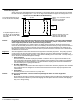
The motor should be installed in a location compatible with the motor enclosure and specific ambient. To
allow adequate air flow, the following clearances must be maintained between the motor and any
obstruction:
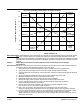
Table 2−1 Enclosure Clearance
TEFC / TENV ( IC0141 ) Enclosures
Fan Cover Air Intake 180 − 210T Frame 1 25mm)
Fan Cover Air Intake 250 − 449T Frame 4 100mm)
IEC 112 − 132 1 25mm)
IEC 160 − 280 4 100mm)
Exhaust Envelope equal to the P Dimension on the motor
dimension sheet
OPEN/Protected Enclosures
Bracket Intake Same as TEFC
Frame Exhaust Exhaust out the sides envelope
A minimum of the P dimension plus 2 (50mm)
Exhaust out the end same as intake.
The motor must be securely installed to a rigid foundation or mounting surface to minimize vibration and
maintain alignment between the motor and shaft load. Failure to provide a proper mounting surface may
cause vibration, misalignment and bearing damage.
Foundation caps and sole plates are designed to act as spacers for the equipment they support. If these
devices are used, be sure that they are evenly supported by the foundation or mounting surface.
When installation is complete and accurate alignment of the motor and load is accomplished, the base
should be grouted to the foundation to maintain this alignment.
The standard motor base is designed for horizontal or vertical mounting. Adjustable or sliding rails are
designed for horizontal mounting only. Consult your Baldor distributor or authorized Baldor Service Center
for further information.