
User guide

Page 7 55048-04_97_A
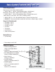
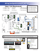
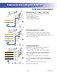
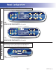
Electrical Service Configuration Options
T
B
1
B
alboa
J68
J68
J101
J101
J100
J100
J
26
J53
J53
J99
J99
J27
J2
J2
J27
J32
J32
J
2
8
J
23
J
95
J
9
4
J
57
J
9
6
J
9
3
F6
F
7
K7
FUSE T30A 480
V
J
59
J
58
W4
W3
BALBOA INSTRUMENTS
,
INC.
GL2000 T
C
MA
C
H 3
P
/
N 22898 REV D
CO
PYRI
G
HT 2006
M
ADE IN U.
S
.A
.
F1
H
T
R
H
2
HTR1
H
T
B
1
B
a
l
boa
J68
J68
J101
J101
J100
J100
J
26
J53
J53
J99
J99
J27
J2
J2
J27
J32
J32
J
2
8
J
23
J
95
J
9
4
J
57
J
9
6
J
9
3
F6
F7
K7
FUSE T30A 480
V
J
59
J
58
W4
W3
BALBOA INSTRUMENTS
,
INC.
GL2000 T
C
MA
C
H 3
P
/
N 22898 REV D
CO
PYRI
G
HT 2006
M
ADE IN U.
S
.A
.
F1
H
T
R
H
2
HTR1
H
T
B
1
B
alboa
J68
J68
J101
J101
J100
J100
J
26
J53
J53
J99
J99
J27
J2
J2
J27
J32
J32
J
2
8
J
23
J
95
J
9
4
J
57
J
9
6
J
9
3
F6
F
7
K7
FUSE T30A 480
V
J
59
J
58
W4
W3
BALBOA INSTRUMENTS
,
INC.
GL2000 T
C
MA
C
H 3
P
/
N 22898 REV D
CO
PYRI
G
HT 2006
M
ADE IN U.
S
.A
.
F1
H
T
R
H
2
HTR1
H
L1
N1
L1
N1
L3
L2
L1
N1
L2
N2
Single Service (1 x 16 Amp or 1 x 32 Amp)
This option is configured and shipped as the default.
For 1 x 32 Amp Service:
DIP Switch A2 can be ON
For 1 x 16 Amp Service:
DIP Switch A2 must be OFF
Dual Service Option (2 x 16 Amp)
Completely remove the white wire from J26 and J32.
DIP Switch A2 must be ON
Note: J32 and J23 are electrically identical. The white
wire may be attached to either terminal before removal.
3-Phase Service Option
Completely remove the white wire from J26 and J32.
Note: J32 and J23 are electrically identical. The white
wire may be attached to either of these terminals
before removal.
Completely remove the blue wire from J28 and J57.
Note: J57, J58 and J59 are electrically identical. The blue
wire may be attached to any of these terminals before
removal.
Move the brown wire from J23 or J32 to J28.
DIP Switch A2 must be ON
IMPORTANT - Service MUST include a neutral wire,
with a line to neutral voltage of 230VAC.
For DIP Switch Configured System