
User guide

Page 5 55048-04_97_A
T
B
1
B
a
l
boa
G
N
G
N
G
N
G
N
G
N
G
N
J68
J68
J101
J101
J100
J100
J
26
J53
J53
J99
J99
J97
J97
W15
J27
J2
J2
J27
J32
J32
J
55
J
90
J1
T1
J
5
6
J
6
0
J
3
3
3
J41
J41
J45
J45
J2
W1
F4
W2
J
8
1
J31
J31
J
1
2
J30
J30
J
2
8
J
23
J
9
8
J54
J54
J54
J54
J
7
9
J
9
5
J
94
J14
J14
J
57
J
9
6
J
9
3
F6
F7
K7
K6
K
8
FUS
E T30A 480V
FUS
E F10A 250
V
FUSE T30A 480
V
J
59
J
58
J
5
K3
W4
K2
F5
J3
J
4
F
2
F
US
E T0.2
A
240
V
K4
K11
K10
K9
K1
J9
N
G
W3
B
ALB
O
A IN
S
TRUMENT
S
, IN
C.
G
L2000 T
C
MA
C
H
3
P
/N 22898 REV
D
CO
PYRI
G
HT 2006
M
ADE IN
U
.
S
.A.
J
1
3
J
1
5
J7
J
8
2
J
2
2
J
24
EXT RELAY J6
E
XT 2
S
P
3
A
U
X
F
A
LAR
M
S
EN A VA
C
S
EN B
J
8
3
J
9
1
C
F
G
J
1
7
T
S
T
S
WIT
C
HBANK A
S
WIT
C
HBANK
B
FU
S
E F3A 250
V
AD
CM
MAIN
PAN
E
L
MAIN
PAN
EL
MAIN
PAN
EL
A
UX
PAN
E
L
AUX
PAN
EL
REM
O
TE
J
6
9
J
2
0
J71 J72
J
70
J
10
J
39
F1
H
TR
H
2
H
TR1
H
E
XT I
/O
J
3
6
J8
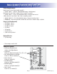
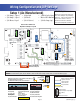
Ozone
3.0 kW
3.0kW
Heater rated @ 240V
J8 must be Jumpered
RTC
Enabled
A.V.
Circ Pump
Spa
Light
Blower
Use X-P CE or X-P231 CE
Expander for Pump 3 1-Speed
1-Spd P2
2-Spd P1
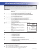
Wiring Configuration and DIP Settings
Setup 1 (As Manufactured)
s 60UMP3PEED
s 60UMP3PEED
s 6"LOWER3PEED
s 63PA,IGHT
s 6/ZONE
s 6!<6(Stereo)
s
K7)NCOLOY(EATER
s
ML900 or ML700 Main Panel
s 6#IRC0UMPOPT
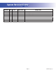
Switchbank A Switchbank B
A2, Low Amp
A5, Degrees F
A6, Short Timeouts
A9/A10,
No Circ Pump
A9/A10,
No Circ Pump
A1, Test Mode OFF
A3, Filter by Time
A4, 12 Hr Time
A7, Cleanup Cycle OFF
A8, 1Hr O
3
Supress OFF
A12, Memory Retained
B1, Pump 2 2-Speed
B2, Pump 2 Disabled
B3, Blower Disabled
B4, No Fiber/Wheel
B5, Pump 3 Disabled
B6, Panel Scrunching OFF
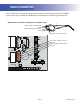
J91
RTC
Enabled
(Not Jumpered)
J8
3.0kW
Heater
J83
CFG
When the Logic Jumper is not installed on J83 (CFG),
DIP Switch Settings are enabled.
DIP Switches will then operate as shown below.
B3, Blower Enabled
B2, Pump 2 Enabled
B1, Pump 2 1-Speed
A11, O
3
w/ P1 Low
and P1 is 2-Spd
A5, Degrees C
A2, High Amp
100
119
32
SSID #
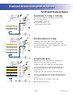
Neutral (Common) AC Connections
Special AC Connections
Line AC Connections
10 Volt Connections
Relay Control Wires
Wiring Color Key
Typically Line voltage
Typically Line voltage for 2-speed pumps
Neutral (Common)
Ground
Note flat sides in connector
Board Connector Key
1
2
3
4
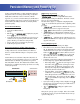
WARNING: Main Power to system should be turned OFF BEFORE adjusting DIP switches.
WARNING: Persistent Memory (A12) must be RESET to allow new DIP switch settings to take effect. (See Persistent Memory page)
HIPot Testing Note:
Disconnect slip terminal with green
wires from J90 prior to performing
HiPot test. Failure to disconnect will
cause a false failure of the test.
Reconnect terminal to J90 after
successful completion of HiPot test.