GL2000 Mach 3 Tech Sheet Balboa Instruments System PN 55048-04 System Model # GL2-GL2000M3-RCA-3.0 Software Version # 32 EPN # 2833 Base PCBA – PN 53708-04 PCB GL2000 – PN 22898 Rev B, C, or D HEX File – 10011932 Base Panels ML900 – PN 52654-01 ML700 – PN 52649-01 ML400 – PN 52684 Template used: 40597-v32_A.pdf 04/15/2008 55048-04_97_A.
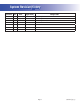
System Revision History System PN EPN 55048-02 55048-03 55048-04 Date Requested By 2130 12.06.2006 Balboa n/a 07.23.2007 Balboa 2833 05.06.
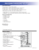
Basic System Features and Functions Power Requirements Single Service [3 wires (line, neutral, ground)] s 6!# (Z ^ ! ! #IRCUIT "REAKER RATING ! ! MAX Dual Service [5 wires (line 1, neutral 1, line 2, neutral 2, ground)] s 6!# (Z ^ X ! #IRCUIT "REAKER RATING ! MAX EACH SERVICE 0HASE 3ERVICE ; WIRES LINE LINE LINE NEUTRAL GROUND = s 6!# (Z .^ ! #IRCUIT "REAKER RATING ! MAX EACH PHASE LINE s )-0/24!.
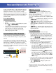
Persistent Memory and Powering Up Any time you change DIP Switches or Software Configuration Settings that affect parameters the user can change (any filter settings, set temperature default, Celsius vs Fahrenheit, 12-hour vs 24-hour time, reminders suppression, etc), you must reset Persistent Memory for your DIP Switch or Software Configuration Settings changes to take effect. You should also reset Persistent Memory after loading a new file into a board (using the ESM, purchased seperately).
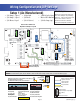
Wiring Configuration and DIP Settings HIPot Testing Note: Setup 1 (As Manufactured) s 6 0UMP 3PEED s 6 0UMP 3PEED s 6 "LOWER 3PEED s 6 3PA ,IGHT s 6 /ZONE s 6 !<6 (Stereo) Disconnect slip terminal with green wires from J90 prior to performing HiPot test. Failure to disconnect will cause a false failure of the test. s K7 )NCOLOY (EATER s ML900 or ML700 Main Panel s 6 #IRC 0UMP OPT Reconnect terminal to J90 after successful completion of HiPot test.
DIP Switches and Jumpers Definitions WARNING: sSetting DIP switches incorrectly may cause abnormal system behavior and/or damage to system components. sRefer to Switchbank illustration on Wiring Configuration page for correct settings for this system. sContact Balboa if you require additional configuration pages added to this tech sheet. DIP Switchbank A Key A1 . . . . . . . . . . . . . . . . Test Mode (normally Off) A2 . . . . . . . . . . . . . . . .
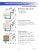
Electrical Service Configuration Options For DIP Switch Configured System J32 F6 Single Service (1 x 16 Amp or 1 x 32 Amp) J99 J53 MADE IN U.S.A. J23 J94 Balboa BALBOA INSTRUMENTS, INC. GL2000 TC MACH 3 P/N 22898 REV D COPYRIGHT 2006 TB1 F7 J2 J27 J93 J95 FUSE T30A 480V W3 J28 J96 J26 L1 This option is configured and shipped as the default.
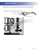
Ozone Connections Note: A special tool is required to remove the pins from the connector body once they are snapped in place. Check with your Balboa Account Manager for information on purchasing a pin-removal tool.
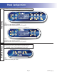
Panel Configurations Note: RTC jumper (J91) on Main PCBA must be OFF (1 pin only) Time Warm Jets 1 Jets 2 Jets 3 Option Mode/Prog Cool Invert Fiber Light Blower F1 F2 PL TIME CAPABLE TL ML900 PN 52654-01 with Overlay PN 40026 s Connects to Main Panel terminal J70, J71, or J72 Time Warm Light Blower Mode/Prog Cool Jets 1 Jets 2 F1 F2 PL TL NON-TIME CAPABLE ML700 PN 52649-01 with Overlay PN 11281 s Connects to Main Panel terminal J70, J71, or J72 Note: Connects to Main Panel terminal