
Installation Manual
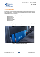
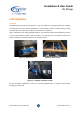
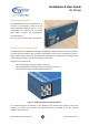
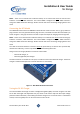
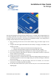
Table Of Contents

Slimline Battery User Guide 2021 www.baintech.com.au
Installation & User Guide
SL Range
9
NOTE – There are no internal fuses inside the battery so an external fuse must be used for each
Anderson connector, 100A maximum. The internal BMS is designed for up to 100A continuous
charge and 100A continuous discharge. Please consider this when connecting charging devices and
loads.
Connecting the DCS Model
The BAINTECH-1275-SL-DCS and BAINTECH-12110-SL-DCS model contains one (1) grey Anderson
plug connector and one (1) blue Anderson plug connector, accessible from the side of the battery as
shown in Figure 4. The grey connector can used as input and output for charging and running loads.
NOTE – There are no internal fuses inside the battery so an external fuse must be used for the grey
Anderson connector, 100A maximum. The internal BMS is designed for up to 100A continuous
charge and 100A continuous discharge. Please consider this when connecting charging devices and
loads.
The cable to the blue Anderson connector should be protected by an external fuse (at least 20A,
rated for the cable size), as close as possible to the vehicle battery/alternator.
Charge sources to the grey Anderson connector could include:
- External AC charger; or
- External (regulated) solar charger.
The blue connector is reserved for a DC input, to make use of the internal DC-DC charger. The DC-DC
charger is rated for 20A input from a vehicle alternator or start battery.
Figure 4 – DCS Model Anderson Connectors
Tuning the DC-DC Charger
The internal 20A DC-DC charger contains a Voltage Sensing Relay (VSR). As shown in Figure 5 the VSR
has an LED status light and adjustment trim pot, which can be used to adjust at what input voltage
(from the vehicle alternator / start battery) the DC-DC charger turns on and off. There is a dead-band
of 0.5V, so that it typically turns on at 13.3V and turns off at 12.8V.