
User's Manual


First InterComm™ system VCA100 user manual A29798 September 20088
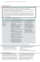
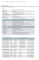
Table 1. VCA100 troubleshooting procedures
IMPORTANT
– If the First InterComm system appears to interfere with incident site
operations, immediately turn off every VCA100 unit and Talk Group software in
use and return to normal operating procedures.
– If Talk Group software or laptop computer problems occur, the VCA100 units
will remain in their assigned talk groups. If the laptop or Talk Group software
is not functional and communication is needed among all responders, cycle
power to all VCA100s. This entails turning off the power to the VCA100 and
then repowering.
Troubleshooting
– Land mobile radio antenna matched
to user’s existing radio network
frequencies.
– Remote on/off switch.
– Talk Group software (optional capability).
pre-designated interoperability channel
to monitor or speak to members of other
radio networks at the site. The specific
VCA100 model is based on the radio
frequencies used by the participating
department (see Appendix A).
The First InterComm system consists of:
– VCA100 unit matched to user’s
existing radio network frequencies.
– Vehicle-mounted wireless antenna.
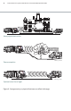
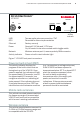
The VCA100 unit (Figure 7) is vehicle-
mounted and has no operator controls
other than a remote power-on switch. Once
the VCA100 is initialized, operations are
transparent to the operator, responders
need only set their radio equipment to the
First InterComm system component descriptions
The VCA100 unit
Problem Action Comments
No
communications
via First
InterComm
systems
1. Verify indicator on power
switch is lit. If not, verify that
fuse is good.
2. Verify the activity indicator on
VCA100 front panel is lit.
3. Verify all communication
devices are using the
designated interoperability
channel.
4. Verify at least two VCA100s
are in the incident area and
power has been applied
to the units for at least 60
seconds.
5. Verify each VCA100 wireless
antenna has clear LOS to
other wireless antennas.
6. Verify distance between
VCA100 wireless antennas
is a quarter mile or less.
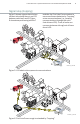
1. If the activity indicator
is not easily viewed,
a secondary power
indication is an amber
LED in the lower right
corner of the Ethernet
connector (Figure 7).
2. If the fuse is good,
but there is no power
indication, contact
maintenance personnel.