
Installation Guide

First InterComm
™
System VCA100 Installation Guide
Page 2 A29799
PROPRIETARY INFORMATION: This document contains trade secrets and commercial or financial information that is the property of BAE
Systems Electronics and Integrated Solutions (E&IS). Further dissemination or disclosure of this information is strictly prohibited without
the written permission of BAE Systems.
B.2 Serial IP Program ....................................................................................... 26
B.3 Kenwood Radio Programming Software..................................................... 27
Appendix C Acronyms and Abbreviations................................................................ 29
Appendix D Troubleshooting Procedures ................................................................ 30
Appendix E Installation Sign Off Sheet..................................................................... 31
List of Illustrations
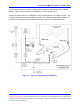
Figure 1. Typical VCA100 Vehicle Installation................................................................ 7
Figure 2. First InterComm™ System VCA100 Unit ....................................................... 8
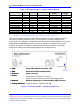
Figure 3. VCA100 Power Harness Connector – Front View........................................... 9
Figure 4. Standard Comtelco WiFi Antenna................................................................... 9
Figure 5. In-Line Fuse .................................................................................................. 13
Figure 7. VCA100 Mounting Bracket............................................................................ 14
Figure B-1.1 First InterComm™ VCA Manager Window ............................................. 23
Figure B-1.2 VCA Manager Internet Explorer Window................................................. 24
Figure B-1.3 VCA Manager Configuration Window ...................................................... 24
Figure B-1.4 First InterComm™ VCA Manager Help Window..................................... 25
Figure B-2.1 Serial IP Control Panel and Select Port Windows ................................... 26
Figure B-2.2 Serial IP Program Configuration Wizard.................................................. 27
List of Tables
Table 1. First InterComm™ System VCA100 Models ................................................... 8
Table 2. VCA 100 Vehicle Installation Kit..................................................................... 10
Table 3. Installer-Supplied Parts .................................................................................. 10
Table 4. Required Equipment and Software................................................................. 11
Table 5. Recommended Tools for First InterComm™ System Installation.................. 11
Table 6. Initial Power Tests.......................................................................................... 17
Table 7. Required User Information ............................................................................. 18
Table 8. VCA100 Update Procedure............................................................................ 19
Table 9. LMR Antenna VSWR Test Results................................................................. 20
Table 10. System Functional Test Results................................................................... 20
Table A-1. Recommended LMR Antennas................................................................... 22
Table A-2. LMR Antenna Specifications....................................................................... 22
Table B-1 VCA100Model Characteristics...................................................................... 28
Table B-2 Required Kenwood Radio Parameters To Be Programmed ......................... 28