
Installation Guide

First InterComm
™
System VCA100 Installation Guide
A29799 rev A Page 17
PROPRIETARY INFORMATION: This document contains trade secrets and commercial or financial information that is the property of BAE
Systems Electronics and Integrated Solutions (E&IS). Further dissemination or disclosure of this information is strictly prohibited without
the written permission of BAE Systems.
6. Use cable ties and mounts to protect the wire. Grommet all through holes to prevent
cable chaffing. Install VCA100 Fuse.
5.0 Initial Power Test
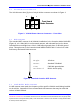
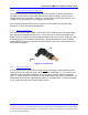
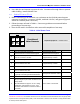
1. Before connecting to the VCA100, use a voltmeter at the VCA100 power harness
connector to check for a constant +12VDC, switched +12VDC, and ground (Figure 3
shows the VCA100 power connector).
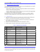
2. Follow the steps as listed in Table 6. Correct any problems encountered before
proceeding to the next step.
3. Place check mark in Verified box after successful completion of test step.
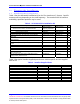
Table 6. Initial Power Tests
Required Equipment: Volt/Ohm Meter
Step Procedure Expected Result Verified
1
Verify VCA100 power harness is
disconnected from VCA100 and energized
VCA100 power harness
disconnected and energized
2
Probe the VCA100 power harness connector
Pin 1 for a constant +12 VDC
Voltmeter reads vehicle power
as approximately +12VDC
3 Set the VCA100 power switch to ON Power switch is ON
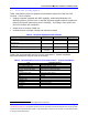
4
Probe the VCA100 power harness connector
pin 2 for switched +12 VDC
Voltmeter reads vehicle power
as approximately +12VDC
5 Set the VCA100 power switch to OFF VCA100 is OFF
6
Probe the VCA100 power harness connector
pin 2 for switched +12 VDC
Voltmeter reads 0 VDC
7
Probe VCA100 power harness connector pin
4 (ground) to chassis ground with ohmmeter
Good ground connection exists
8 Connect VCA100 power harness to VCA100. Items are connected.
9
Turn on VCA100 unit and monitor Activity
LED (see Figure 2) for Power On Built In Test
(PBIT) Result.
LED will illuminate for approx. 30 sec. during
initialization, extinguishes for 10 sec., then
illuminates and remains on if Power-on BIT is
successful.
Power-on BIT is successful.
Front View of
Molex Connecto
r
Front View of
Molex Connecto
r
1 2 3
4 5 6
1 2 3
4 5 6
1 2 3
4 5 6
NC
+12
Switch
+12
VDC VDC
NC
+12
VDC
Pwr
+12
VDC
Pwr
NC
Gnd