
Installation Guide

First InterComm
™
System VCA100 Installation Guide
A29799 rev A Page 15
PROPRIETARY INFORMATION: This document contains trade secrets and commercial or financial information that is the property of BAE
Systems Electronics and Integrated Solutions (E&IS). Further dissemination or disclosure of this information is strictly prohibited without
the written permission of BAE Systems.
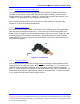
3. Run the RF cable from the WiFi antenna to the VCA100. Use cable ties and
mounts to protect the cable. Grommet all through holes to prevent cable chaffing.
4. Connect the WiFi RF cable in a straight path to the VCA100 NETWORK A SMA
connector. Use cable ties and mounts to keep the cable from moving or placing
stress on the SMA connector.
4.3 Land Mobile Radio Antenna
1. Carefully inspect the area selected for the LMR antenna to ensure that the area is
free of physical or electrical obstacles that could interfere with proper installation,
maintenance, or operation.
2. Follow the LMR manufacturer’s installation instructions for mounting of the
antenna and for trimming it to the user’s frequency.
3. Run the RF cable from the LMR antenna to the VCA100. Use cable ties and
mounts to protect the cable. Grommet all through holes to prevent cable chaffing.
4. At the VCA100, lay in a stress relief loop and cut the LMR RF cable to length.
Terminate the cable with a TNC connector in accordance with manufacturer’s
instructions. Connect to the VCA100 LMR TNC connector.
4.4 DC Power
1. Carefully inspect the area selected for the DC power lines to ensure that the area is
free of physical or electrical obstacles that could interfere with proper installation,
maintenance, or operation.
2. Starting at the VCA100, locate a suitable chassis ground as close to the VCA100 as
possible. If necessary, scrape and remove paint to reach bare metal. Drill chassis
and use a self-tapping screw and star washer to create a chassis ground.
3. Locate the 20 AWG ground (black) wire of the VCA100 power harness (Pin 4). Cut
and strip the outer cable jacket as required. Cut the end of the ground wire to
length, terminating with a ring terminal, and secure the terminal to the chassis
ground created in Step 2 (see Figure 3).
4. Lay in a stress relief loop and use cable ties and mounts to secure the power
harness to the vehicle and prevent vibration or strain on the power connector.
5. Connect a suitable length of red 16 AWG wire to the VCA100 power harness main
power (red) wire (Pin 1) (see Figure 3) using the 16 to 20 step-down environmental
splice (SUPPLIED). Run the other end of the wire to the VCA100 in-line fuse. Use
cable ties and mounts to protect the cable. Grommet all through holes to prevent
cable chaffing.
6. Connect a suitable length of orange 20 AWG wire to the VCA100 power harness
12V Switch (white) wire (Pin 2) (see Figure 3) using the 20 AWG environmental
splice (SUPPLIED). Run the other end of the wire to the planned location of the