
Installation Guide

First InterComm
™
System VCA100 Installation Guide
Page 14 A29799
PROPRIETARY INFORMATION: This document contains trade secrets and commercial or financial information that is the property of BAE
Systems Electronics and Integrated Solutions (E&IS). Further dissemination or disclosure of this information is strictly prohibited without
the written permission of BAE Systems.
4.0 Installation Procedures
4.1 VCA100 Unit
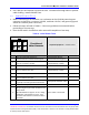
1. Record the VCA100 model number and serial number on the INSTALLATION SIGN
OFF SHEET (see Appendix E). Tag is not viewable after mounting.
2. Carefully inspect the area selected for the VCA100 unit to ensure that the area is
free of physical or electrical obstacles that could interfere with proper installation,
maintenance, or operation.
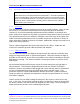
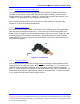
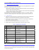
3. Attach the two L-shaped mounting brackets (Figure 6) to the sides of the VCA100
using four #6-32 countersunk machine screws if holes are used, or thumbscrews if
quick-release slots are used. Attach the wide edge of the bracket to the VCA100;
attach the narrow edge to the vehicle.
4. Place the VCA100 in its final location and scribe three bracket holes into the
vehicle on each side of the VCA100 for drilling. The VCA100 must be firmly
mounted to the vehicle.
5. Pre-drill six holes into the vehicle to accommodate self-tapping screws. The size
of the hardware used determines the size of the holes.
6. Mount the VCA100 to the vehicle with self-tapping screws.
Figure 6. VCA100 Mounting Bracket
4.2 WiFi Antenna
1. Verify the center pin of the WiFi antenna cable connector is female (reverse
polarity SMA). Carefully inspect the area selected for the WiFi antenna to ensure
that the area is free of physical or electrical obstacles that could interfere with
proper installation, maintenance, or operation.
2. Follow manufacturer’s installation instructions for external mounting of the WiFi
antenna.