
Installation Guide

First InterComm
™
System VCA100 Installation Guide
A29799 rev A Page 13
PROPRIETARY INFORMATION: This document contains trade secrets and commercial or financial information that is the property of BAE
Systems Electronics and Integrated Solutions (E&IS). Further dissemination or disclosure of this information is strictly prohibited without
the written permission of BAE Systems.
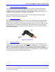
3.3.3 Land Mobile Radio Antenna
The LMR antenna must match the frequency of the specific VCA100 model being
installed on the vehicle. Many LMR antennas will require cutting to ensure proper
VSWR match on the customer’s frequency. Ensure that the new LMR antenna is not
installed in close proximity to any existing LMR antennas.
We recommend keeping the antenna at least 12 inches away from any light bars,
antennas, or other roof-mounted equipment.
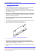
3.3.4 Power and Fuse
The vehicle’s main power source is connected to the VCA100 by the DC power cable
(red) that passes through an inline fuse. Locate the fuse as close as possible to the
power source and splice it in with weatherproof butt splices (SUPPLIED). Mount the fuse
assembly (Figure 5) to facilitate maintenance. Splice the power line to the VCA100
power harness (SUPPLIED) using the step-down splice (SUPPLIED) to accommodate the
dissimilar wire gauges.
Figure 5. In-Line Fuse
3.3.5 Manual Switch
A second, low current, power line (orange) must run through a cab-mounted manual
toggle switch to the VCA100 power connector S
WITCH input (pin 2). This switch is not
supplied in the deliverable installation kit because User-specific vehicle installations
vary; i.e., switch location is a function of User requirements and vehicle constraints. An
illuminated manual switch, appropriately labeled, is recommended. Connect the switch
to a 1-ampere fuse-protected vehicle power source.