
Installation Guide

First InterComm
™
System VCA100 Installation Guide
A29799 rev A Page 9
PROPRIETARY INFORMATION: This document contains trade secrets and commercial or financial information that is the property of BAE
Systems Electronics and Integrated Solutions (E&IS). Further dissemination or disclosure of this information is strictly prohibited without
the written permission of BAE Systems.
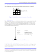
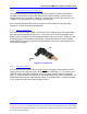
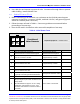
2.2 VCA100 Power Connector
The VCA100 uses three (3) pins of a 6-pin Molex connector as shown in Figure 3.
Figure 3. VCA100 Power Harness Connector – Front View
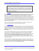
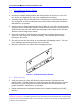
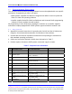
2.3 WiFi Antenna
The standard WiFi antenna for all VCA100 installations is the Comtelco Model A10245B
(Figure 4), a 2.4 GHz 802.11 roof mounted antenna, with elevated feed to rise above
cab obstructions and light bars. Gain is 3 dBi without ground plane, 5 dBi with ground
plane. Through mount is the Comtelco Model MBZM-10R/PI with 14’ micro-loss cable
and factory terminated SMA connector.
Figure 4. Standard Comtelco WiFi Antenna
2.4 Land Mobile Radio Antenna
A LMR antenna must match the frequency of the specific VCA100 model being installed
on the vehicle. Appendix A lists recommended LMR antennas that may be used with
various VCA100 models.
Front View of
Molex Connecto
r
Front View of
Molex Connecto
r
1 2 3
4 5 6
1 2 3
4 5 6
1 2 3
4 5 6
NC
+12
Switch
+12
VDC VDC
NC
+12
VDC
Pwr
+12
VDC
Pwr
NC
Gnd
Height: 14 inches
Mount: Standard TAD/NMO
Gain: 5 dBi with ground plane
Mechanical: Built-in shock spring