
Installation Guide

First InterComm
™
System VCA100 Installation Guide
Page 8 A29799
PROPRIETARY INFORMATION: This document contains trade secrets and commercial or financial information that is the property of BAE
Systems Electronics and Integrated Solutions (E&IS). Further dissemination or disclosure of this information is strictly prohibited without
the written permission of BAE Systems.
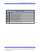
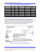
Table 1. First InterComm™ System VCA100 Models
Model Protocol Encryption LMR Band Kenwood Radio
Module
Frequency
Range
VCA100-L1FCGX FM None VHF Low Band TK-190K 29.7 – 37 MHz
VCA100-L2FCGX FM None VHF Low band TK-190K2 35 – 50 MHz
VCA100-V1FCGX FM None VHF High Band TK-2180K 136 - 174 MHz
VCA100-V1PCGX FM/P25 None VHF High Band TK-5210K 136 - 174 MHz
VCA100-V1PAGX FM/P25 DES/AES VHF High Band TK-5210K 136 - 174 MHz
VCA100-V1PDGX FM/P25 DES VHF High Band TK-5210K 136 - 174 MHz
VCA100-U1FCGX FM None UHF TK-3180K 450 - 520 MHz
VCA100-81FCGX FM None 800 TK-480SK 806 - 870 MHz
VCA100-81PCGX FM/P25 None 800 TK-5400K 806 - 870 MHz
VCA100-81PDGX FM/P25 DES 800 TK-5400K 806 - 870 MHz
VCA100-91FCGX FM None 900 TK-481SK 896 - 941 MHz
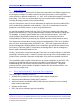
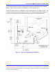
2.1 Vehicle Communications Assembly, Model VCA100
The VCA100 (Figure 2 below) is mounted in a vehicle and has no operator controls
other than a remote power-on switch. Once initialized, VCA100 operations are
transparent to the operator. Responders need only set their radio equipment to the pre-
designated interoperability channel to monitor or speak to members of other radio
networks at the site. The specific VCA100 model is selected based on the radio
frequencies used by the participating department (see Appendix A).
Figure 2. First InterComm™ System VCA100 Unit
•
LMR
: 2 - way radio antenna connection, TNC.
•
GPS
: Reserved for future implementation.
•
Ethernet
: Factory use only.
•
Power
:
•
Network
: Wireless antenna port A, reverse polarity SMA connector.
•
Activity Indicator:
Power On, Built in Test indicator light.
•
LMR
: 2 - way radio antenna connection, TNC.
•
GPS
: Reserved for future implementation.
•
Ethernet
: Factory use only.
•
Power
: Nominal 13.6V DC and 1.75 A max
•
Network
: Wireless antenna port A, reverse polarity SMA connector.
•
Activity Indicator:
Activity
Indicator
On/Off control is via cab mounted switch toggle switch