A29799 rev A May 2008 First InterComm™ System VCA100 Installation Guide ** NOTE: if time permits this manual will be laid out in 8x10 format w/ spiral binder by the Media dept and made to look similar to other FISC manuals at the completion of stake holder review. Page breaks and column formatting will be different. Graphics will be cleaned up. Intended audience is sub-contracted 2-way shops that have signed a NDA and have a SOW.
© 2007, BAE Systems Information and Electronic Systems Integration Inc.. All rights reserved The information contained in this manual is the property of BAE Systems and is intended for the purchaser’s use only. It may not be reproduced without the express written consent of BAE Systems. PROPRIETARY INFORMATION: This document contains trade secrets and commercial or financial information that is the property of BAE Systems Electronics and Integrated Solutions (E&IS).
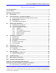
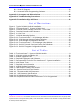
First InterComm™ System VCA100 Installation Guide Table of Contents List of Illustrations ........................................................................................................ 2 List of Tables ................................................................................................................. 2 Warnings and Precautions ........................................................................................... 3 1.0 Introduction...............................................
First InterComm™ System VCA100 Installation Guide B.2 Serial IP Program ....................................................................................... 26 B.3 Kenwood Radio Programming Software..................................................... 27 Appendix C Acronyms and Abbreviations................................................................ 29 Appendix D Troubleshooting Procedures ................................................................ 30 Appendix E Installation Sign Off Sheet ...
First InterComm™ System VCA100 Installation Guide Warnings and Precautions Federal Communications Commission (FCC) Compliance - This equipment has been tested and found to comply with the limits for a Class B digital device, pursuant to Part 15 of the FCC Rules. These limits are designed to provide reasonable protection against harmful interference in a residential environment.
First InterComm™ System VCA100 Installation Guide General Precautions • DC Power – Ensure that power into the First InterComm™ System does not exceed 24VDC. • Explosive Environments – Ensure the First InterComm™ System is turned off before entering a blasting area, or in areas posted “TURN OFF TWO-WAY RADIO”. Sparks in a potentially explosive atmosphere can cause an explosion or fire resulting in bodily injury or death.
First InterComm™ System VCA100 Installation Guide First InterComm System Installation Checklist Plan First InterComm™ System (FICS) equipment locations on the vehicle, Section 3. Perform Vehicle Installation, Section 4. Perform DC Power Test, Section 5 Fill out Table 7, “Required User Information”. Provide copies to Customer, and BAE Systems, and retain file copy. Perform VCA100 Programming, Section 6. Perform Unit Test Plan, Section 7. Fill out “Installation Sign Off Sheet”, Appendix E.
First InterComm™ System VCA100 Installation Guide 1.0 Introduction The First InterComm™ System (FICS) allows first responders from different agencies at an emergency incident to readily communicate with one another, even though their radios operate on different frequencies; i.e., VHF, UHF or 800 MHz systems, both digital and analog. The FICS can accommodate any new communication technologies, including operating systems in the 700-MHz band.
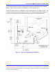
First InterComm™ System VCA100 Installation Guide The system operates on 12VDC vehicle power through an independent cab-mounted switch. There are no speakers, microphones, or other vehicle tie-ins. Eleven VCA100 models are available to cover the LMR bands (see Table 1 below). The LMR antenna must match the frequency band of the VCA100 model being installed. A standard, roof mounted 2.4 GHz 802.11 antenna is used for all VCA100 models. Figure 1.
First InterComm™ System VCA100 Installation Guide Table 1. First InterComm™ System VCA100 Models Model Protocol Encryption LMR Band VCA100-L1FCGX VCA100-L2FCGX VCA100-V1FCGX VCA100-V1PCGX VCA100-V1PAGX VCA100-V1PDGX VCA100-U1FCGX VCA100-81FCGX VCA100-81PCGX VCA100-81PDGX VCA100-91FCGX FM FM FM FM/P25 FM/P25 FM/P25 FM FM FM/P25 FM/P25 FM None None None None DES/AES DES None None None DES None VHF Low Band VHF Low band VHF High Band VHF High Band VHF High Band VHF High Band UHF 800 800 800 900 2.
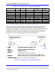
First InterComm™ System VCA100 Installation Guide 2.2 VCA100 Power Connector The VCA100 uses three (3) pins of a 6-pin Molex connector as shown in Figure 3. 4 5 6 Gnd 4 5 NC NC 6 +12 1 VDC Pwr +12 2 VDC Switch 3 NC 1 2 3 Front View of Molex Connector Figure 3. VCA100 Power Harness Connector – Front View 2.3 WiFi Antenna The standard WiFi antenna for all VCA100 installations is the Comtelco Model A10245B (Figure 4), a 2.4 GHz 802.
First InterComm™ System VCA100 Installation Guide 3.0 Planning the Installation 3.1 Installation Kit Components Table 2 lists the deliverable installation kit for the First InterComm™ System. Specific antennas will vary depending on the LMR frequency. The material listed is based on availability; equivalent products may be used. Table 2.
First InterComm™ System VCA100 Installation Guide 3.2 Tools and Test Equipment Table 4 lists details of the test equipment and software required to install the FICS VCA100. These comprise: • A laptop computer equipped with WiFi capability, loaded with Windows® XP1 Operating System, Service Pack 2, and BAE Systems supplied software (required to upload user-specific parameters into the VCA100). The laptop is also used to test the FICS VCA100 after installation. • A watt meter to perform VSWR test.
First InterComm™ System VCA100 Installation Guide 3.3 System Component Locations WARNING WHEN SELECTING LOCATIONS FOR FIRST INTERCOMM™ SYSTEM COMPONENTS, AVOID HIGH FREQUENCY (HF) NOISE PRODUCERS AND DO NOT RUN DC POWER FEEDS TO THE VCA100 PARALLEL TO IGNITION CIRCUITS, ELECTRONIC MODULES, OR SIMILAR ITEMS. AVOID RUNNING POWER LEADS IN PARALLEL WITH VEHICLE WIRING OVER LONG DISTANCES. 3.3.1 VCA100 The VCA100 has no operator interfaces other than an activity indicator.
First InterComm™ System VCA100 Installation Guide 3.3.3 Land Mobile Radio Antenna The LMR antenna must match the frequency of the specific VCA100 model being installed on the vehicle. Many LMR antennas will require cutting to ensure proper VSWR match on the customer’s frequency. Ensure that the new LMR antenna is not installed in close proximity to any existing LMR antennas. We recommend keeping the antenna at least 12 inches away from any light bars, antennas, or other roof-mounted equipment. 3.3.
First InterComm™ System VCA100 Installation Guide 4.0 Installation Procedures 4.1 VCA100 Unit 1. Record the VCA100 model number and serial number on the INSTALLATION SIGN OFF SHEET (see Appendix E). Tag is not viewable after mounting. 2. Carefully inspect the area selected for the VCA100 unit to ensure that the area is free of physical or electrical obstacles that could interfere with proper installation, maintenance, or operation. 3.
First InterComm™ System VCA100 Installation Guide 3. Run the RF cable from the WiFi antenna to the VCA100. Use cable ties and mounts to protect the cable. Grommet all through holes to prevent cable chaffing. 4. Connect the WiFi RF cable in a straight path to the VCA100 NETWORK A SMA connector. Use cable ties and mounts to keep the cable from moving or placing stress on the SMA connector. 4.3 Land Mobile Radio Antenna 1.
First InterComm™ System VCA100 Installation Guide VCA100 On/Off Switch. Use cable ties and mounts to protect the wire. Grommet all through holes to prevent cable chaffing. 4.5 VCA100 On/Off Switch 1. Carefully inspect the area selected for the VCA100 On/Off Switch to ensure that the area is free of physical or electrical obstacles that could interfere with proper installation, maintenance, or operation. 2. Drill or cut an area to hold the lighted toggle switch. Mount and label the switch. 3.
First InterComm™ System VCA100 Installation Guide 6. Use cable ties and mounts to protect the wire. Grommet all through holes to prevent cable chaffing. Install VCA100 Fuse. 5.0 Initial Power Test 1. Before connecting to the VCA100, use a voltmeter at the VCA100 power harness connector to check for a constant +12VDC, switched +12VDC, and ground (Figure 3 shows the VCA100 power connector). 2. Follow the steps as listed in Table 6. Correct any problems encountered before proceeding to the next step. 3.
First InterComm™ System VCA100 Installation Guide 6.0 Programming Procedure The VCA100 is delivered with operating software but must be updated with user-specific parameters. Programming is done in two parts: • BAE Systems’ supplied VCA MANAGER Program and utilities is used to update the flash or to load new operating software. • Installer supplied Serial/IP COM Port Redirector and Kenwood Radio programming software is used to update the radio module.
First InterComm™ System VCA100 Installation Guide 6.2 VCA100 Update Procedure 1. Perform the update in two parts: VCA MANAGER program and Kenwood Radio software. 2. Follow the steps as listed in Table 8. Correct any problems encountered before proceeding to the next step. 3. Place check mark in Verified box after successful completion of test step. Table 8. VCA100 Configuration Procedure Required Items: a. VCA100 Installed in vehicle b. User Parameters (Table 7 of this document). c.
First InterComm™ System VCA100 Installation Guide 7.0 Unit Test Plan Follow the test procedures described in Paragraphs 7.1 and 7.2. Correct any problems found, retest, and record final results on the INSTALLATION SIGN OFF SHEET (Appendix E). 7.1 LMR Antenna VSWR Test Perform an antenna VSWR test using an in-line wattmeter with appropriate frequency range and power levels, and low loss cable and connectors. The LMR output is expected to be in the range of 3 to 5 watts. Record results in Table 9.
First InterComm™ System VCA100 Installation Guide 5 8.0 Verify 2-way communication through both units occurs without distortion, breakup, or dropouts. Record final result on Installation Sign Off Sheet. Communication is good Troubleshooting Appendix D contains detailed troubleshooting procedures for the FICS. IMPORTANT 9.0 • If the FICS appears to interfere with incident site operations, immediately turn off every VCA unit (and FICS Talk Group Software if in use), and return to normal SOP.
First InterComm™ System VCA100 Installation Guide Appendix A Recommended LMR Antennas Table A-1.
First InterComm™ System VCA100 Installation Guide Appendix B VCA100 Software Programs and Utilities B.1 BAE Systems VCA Manager Program The VCA Manager is used to connect wirelessly to the VCA100 in order to change User parameters and upgrade software on the VCA100. The procedure is to: 1. Power up the VCA100(s) that will be updated and then power up the laptop so that a First InterComm Network is established. 2.
First InterComm™ System VCA100 Installation Guide Figure B-1.2 VCA Manager Configuration Tool 5. Enter user name and password in the pop up window and click Validate. (See your BAE Systems representative for your user name and password.) Figure B-1.3 VCA Manager Configuration Window Page 24 A29799 PROPRIETARY INFORMATION: This document contains trade secrets and commercial or financial information that is the property of BAE Systems Electronics and Integrated Solutions (E&IS).
First InterComm™ System VCA100 Installation Guide 6. Fill in the fields with new parameter information. Click on Commit to update. Figure B-1.4 First InterComm™ VCA Manager Help Window 7. Clicking on Help will open the VCA00 manger Help page, which provide detailed information about each of the data fields. 8. If the VCA100 software requires upgrading, click on Upload new software image at the main VCA100 Internet Explorer window (Figure B-1.2).
First InterComm™ System VCA100 Installation Guide B.2 Serial IP Program Serial/IP Redirector software, a utility program, creates a virtual COM port that associates an IP address with a hardware COM port. This allows RS-232 programming with Kenwood software over a wireless link to the VCA100 Radio Module. The procedure is to: 1. Start the VCA MANAGER PROGRAM (Paragraph B.1) to enable access to the First InterComm™ network and the VCA100 being programmed. 2.
First InterComm™ System VCA100 Installation Guide Figure B-2.2 Serial IP Program Configuration Wizard B.3 Kenwood Radio Programming Software Kenwood Radio Programming software is used as a utility program to configure the VCA100 Radio Module. NOTE IT IS REQUIRED TO PROGRAM ALL RADIOS PER THE PARAMETERS IN TABLE B-2 BELOW. The procedure is to: 1. Start the VCA Manager Program and Serial IP program (Paragraph B.1 & B.2 above) to link the COM2 port to the VCA100 being programmed. 2.
First InterComm™ System VCA100 Installation Guide Model Protocol Encryption Frequency Range Kenwood Radio Module VCA100-L1FCGX VCA100-L2FCGX VCA100-V1FCGX VCA100-V1PCGX VCA100-V1PAGX VCA100-V1PDGX VCA100-U1FCGX VCA100-81FCGX VCA100-81PCGX VCA100-81PDGX VCA100-91FCGX FM FM FM FM/P25 FM/P25 FM/P25 FM FM FM/P25 FM/P25 FM None None None None DES/AES DES None None None DES None 29.
First InterComm™ System VCA100 Installation Guide Appendix C Acronyms and Abbreviations ABS AES ATC ATO AWG COM DC DES DHS EMI EMS FCC FICS FM GPS GXL HF HSS IAB IAN IC ID IP LED LMR MIPT NIMS NMO OEM P25 RF SAE SMA SOP SPST TBD TNC UHF VCA VHF VSWR WiFi Antilock Brake System Advanced Encryption Standard Automotive Blade-Type Fuse Automotive Blade-Type Fuse American Wire Gauge Communication (port) Direct current Data Encryption Standard Department of Homeland Security Electromagnetic Interference Emergenc
First InterComm™ System VCA100 Installation Guide Appendix D Troubleshooting Procedures To Be Supplied Page 30 A29799 PROPRIETARY INFORMATION: This document contains trade secrets and commercial or financial information that is the property of BAE Systems Electronics and Integrated Solutions (E&IS). Further dissemination or disclosure of this information is strictly prohibited without the written permission of BAE Systems.
First InterComm™ System VCA100 Installation Guide Appendix E Installation Sign Off Sheet I CERTIFY THAT THE FIRST INTERCOMM™ SYSTEM SUPPLIES AND INSTALLATION SERVICES HAVE BEEN FURNISHED IN ACCORDANCE WITH APPLICABLE CONTRACT REQUIREMENTS.
First InterComm™ System VCA100 Installation Guide THIS PAGE INTENTIONALLY LEFT BLANK Page 32 A29799 PROPRIETARY INFORMATION: This document contains trade secrets and commercial or financial information that is the property of BAE Systems Electronics and Integrated Solutions (E&IS). Further dissemination or disclosure of this information is strictly prohibited without the written permission of BAE Systems.
A29799 rev A April 2008 PROPRIETARY INFORMATION: This document contains trade secrets and commercial or financial information that is the property of BAE Systems Electronics and Integrated Solutions (E&IS). Further dissemination or disclosure of this information is strictly prohibited without the written permission of BAE Systems.