
Hardware Solutions for Gas Utilities Owner manual
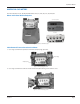

Installation Manual
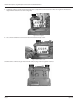
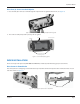
Place Four (4) Screws Into the Endpoint
1. Place the four (4) ¼-20 X 3/8" screws through the endpoint and rear gasket from the front. See Figure 10.
Figure 10: Screw placement from front through endpoint and rear gasket
2. The screws are temporarily held in place by the rear gasket.
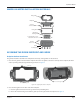
Drain slots towards down and
towards the gas meter
Gasket lip
Tab up
Screws held in place
Figure 11: Screws held in place by gasket
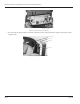
INDEX INSTALLATION
There are two (2) index capacities, ONE-FOOT and TWO-FEET; and two (2) index mounting styles, slots and holes.
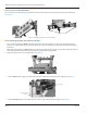
Place Screws in Slotted Index
Place two (2) #8 X ½" self-tapping screws between the top metal dial and the lower plastic frame and into the holes on each
side of the index. See Figure 12.
2 screws
Figure 12: Self-tapping screw placement on slotted index
Page 9 July 2014