
Hardware Solutions for Gas Utilities Owner manual


Installation Manual
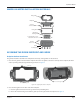
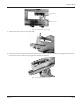
Endpoint pawl
Hole in index pawl
Figure 16: Pawl placement on one-foot dial
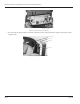
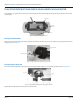
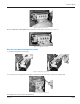
3. Tighten the two (2) screws (6 inch-pounds max).
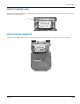
4. Test the drive pawl connection by turning the shaft on the rear of the endpoint several times. If dragging or friction is felt,
reposition the index to eliminate any drag. The dials should turn smoothly.
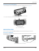
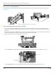
Figure 17: Testing the drive pawl connection
Page 11 July 2014