
Hardware Solutions for Gas Utilities Owner manual

ORION® Gas Endpoints, Integral Endpoint for American® Residential Gas Meters
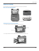
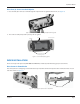
Place Screws in Index With Holes
Place two (2) #8 X ¼" self-tapping screws between the dial and lower plate and into the holes on each side of the meter.
See Figure 13.
2 screws
Figure 13: Self-tapping screw placement on index with holes
Drive Pawl Engagement and Index Installation
1. Use care when handling the ORION endpoint and index to insure the endpoint rear drive pawl and the mating drive
pawls are not subjected to any physical abuse. Abuse may cause the spindles to become bent, misaligned or otherwise
inoperative.
When attaching an index to a ORION endpoint, make sure the index mounts securely to the endpoint. The front and rear
drive pawls must mate without causing any binding or potential for disengagement.
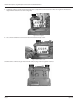
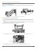
2. Align the two (2) screws in the endpoint holes. See Figure 14.
Figure 14: Align screws in endpoing holes
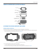
a. On a TWO-FEET dial, engage the index drive pawl into the half round connection in the endpoint. See Figure 15.
Index drive pawl
Half round connection
in endpoint
Figure 15: Drive pawl connection on two-feet dial
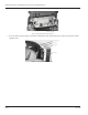
b. On a ONE-FOOT dial, place the index pawl hole into the pawl sticking out of the endpoint. See Figure 16.
Page 10 July 2014