ORION® Gas Endpoints Integral Endpoint for Itron®/Actaris® Residential Slope-Face Gas Meters ORI-UM-00908-EN-06 (July 2014) Installation Manual
ORION® Gas Endpoints, Integral Endpoint for Itron®/Actaris® Residential Slope-Face Gas Meters Page ii July 2014
Installation Manual CONTENTS Disclaimer . . . . . . . . . . . . . . . . . . . . . . . . . . . . . . . . . . . . . . . . . . . . . . . . . . . . . . . . . . . . . . . . . . . . . . . . . . .5 Questions Or Service Assistance . . . . . . . . . . . . . . . . . . . . . . . . . . . . . . . . . . . . . . . . . . . . . . . . . . . . . . . . . . . . .5 Product Identification . . .
ORION® Gas Endpoints, Integral Endpoint for Itron®/Actaris® Residential Slope-Face Gas Meters Page 4 July 2014
Installation Manual DISCLAIMER The user/purchaser is expected to read and understand the information provided in this manual, follow any listed safety precautions and instructions and keep this manual with the equipment for future reference. Misuse, mishandling and/or inadequate maintenance may impair performance and/or compromise safety. QUESTIONS OR SERVICE ASSISTANCE If you have questions regarding the product or this document contact: Badger Meter, Inc. P.O.
ORION® Gas Endpoints, Integral Endpoint for Itron®/Actaris® Residential Slope-Face Gas Meters LICENSE REQUIREMENTS This device complies with Part 15 of FCC Rules. Operation of this device is subject to the following conditions: (1) This device may not cause harmful interference, and (2) this device must accept any interference received, including interference that may cause undesired operation.
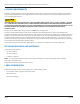
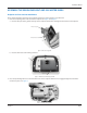
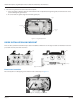
Installation Manual ITRON/ACTARIS SLOPE-FACE MODELS 175/250/400 WITH DIAL OR ODOMETER INDEX (INCLUDING METERS WITH SPRAGUE AND SCHLUMBERGER BRAND NAMES) Odometer style index Dial index Figure 1: Meter and dial or odometer index options INDEX REMOVAL FROM SLOPE-FACE METER 1. Use a large screwdriver to puncture and remove the tamper plugs, if present. 2. Use a large screwdriver to remove and discard the three (3) cover mounting screws and the cover. Figure 2: Remove cover mounting screws 3.
ORION® Gas Endpoints, Integral Endpoint for Itron®/Actaris® Residential Slope-Face Gas Meters 4. Use a small screwdriver to loosen the two (2) index screws. Lift or slide the index to remove it. Figure 4: Remove index 5. Remove and discard the two (2) index mounting screws.
Installation Manual ASSEMBLE THE ORION ENDPOINT AND GAS METER INDEX Endpoint and Lens Gasket Attachment These gaskets should be attached to the endpoint at the factory. If the gaskets are not attached: 1. Place the endpoint gasket on the back of the endpoint. See Figure 7 and Figure 8. a. Place the thin part of the gasket at the top of the endpoint and the tines through the small holes in the endpoint. Thin part of gasket Gasket tines into holes Figure 7: Placement of gasket b.
ORION® Gas Endpoints, Integral Endpoint for Itron®/Actaris® Residential Slope-Face Gas Meters 3. Place the lens gasket on the other side of the endpoint. a. Place the gasket so that the small pin at the bottom of the endpoint fits through the gasket, and the four lens screw posts fit through the gasket holes. b. Be certain that the gasket edge fits around the guide pins.
Installation Manual Place Index on Endpoint Place an index on the endpoint screws and tighten the screws (15 inch-pounds maximum). Figure 13: Place index on endpoint screws Verify that the endpoint pawl and the index odometer or dial pawls mate properly. See Figure 14. Odometer pawl Endpoint pawl Dial pawl Endpoint Pawl Figure 14: Verify endpoint pawls and index pawls mate properly ENDPOINT AND INDEX ON METER Place the endpoint and index on the meter. 1.
ORION® Gas Endpoints, Integral Endpoint for Itron®/Actaris® Residential Slope-Face Gas Meters 2. Screw the endpoint and index onto the gas meter with the three (3) 10-24 X ½" screws (15 in lb. maximum). Figure 16: Screw endpoint and index onto meter 3. Move the odometer or dial TWO-FEET pawls back and forth to verify pawls are connected. See Figure 17. Figure 17: Verify pawls are connected Place the Cover Over the Endpoint and Index 1.
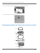
Installation Manual PROGRAM THE ENDPOINT Badger Meter uses a handheld programmer/data collector system to process and display screens. Figure 20: Sample handheld, IR read head and cable Please reference the Programming Guide for ORION gas endpoints and the manual for the handheld system. Programming Procedure To program the endpoint, position the handheld optic read head with the endpoint IR port.
ORION® Gas Endpoints, Integral Endpoint for Itron®/Actaris® Residential Slope-Face Gas Meters Align the IR port of the handheld optic read head with the endpoint IR port. See Figure 22. Figure 22: Line up handheld IR port with endpoint IR port INSERT TAMPER PLUGS After programming the endpoint is complete and for security purposes, insert the four (4) red tamper plugs (supplied) into the screw holes and push them in. See Figure 23.
Installation Manual INTENTIONAL BLANK PAGE July 2014 Page 15
Making Water Visible® MAKING WATER VISIBLE and ORION are registered trademarks of Badger Meter, Inc. Other trademarks appearing in this document are the property of their respective entities. Due to continuous research, product improvements and enhancements, Badger Meter reserves the right to change product or system specifications without notice, except to the extent an outstanding contractual obligation exists. © 2014 Badger Meter, Inc. All rights reserved. www.badgermeter.