ORION® Gas Endpoints Integral Endpoint for Sensus® 415 Gas Meters (2 FT3 Index with 18-Tooth Drive Gear Only) ORI-UM-00903-EN-03 (July 2014) Installation Manual
ORION® Gas Endpoints, Integral Endpoint for Sensus® 415 Gas Meters CONTENTS Disclaimer . . . . . . . . . . . . . . . . . . . . . . . . . . . . . . . . . . . . . . . . . . . . . . . . . . . . . . . . . . . . . . . . . . . . . . . . . . .3 Questions Or Service Assistance . . . . . . . . . . . . . . . . . . . . . . . . . . . . . . . . . . . . . . . . . . . . . . . . . . . . . . . .
Installation Manual DISCLAIMER The user/purchaser is expected to read and understand the information provided in this manual, follow any listed safety precautions and instructions and keep this manual with the equipment for future reference. Misuse, mishandling and/or inadequate maintenance may impair performance and/or compromise safety. QUESTIONS OR SERVICE ASSISTANCE If you have questions regarding the product or this document contact: Badger Meter, Inc. P.O.
ORION® Gas Endpoints, Integral Endpoint for Sensus® 415 Gas Meters LICENSE REQUIREMENTS This device complies with Part 15 of FCC Rules. Operation of this device is subject to the following conditions: (1) This device may not cause harmful interference, and (2) this device must accept any interference received, including interference that may cause undesired operation.
Installation Manual REMOVE OLD INDEX 1. Use a large screwdriver to puncture and remove tamper plugs if they are present. 2. Use a large screwdriver to remove and discard the four (4) mounting screws and the cover. See Figure 2. Figure 2: Remove mounting screws 3. Remove and discard the gasket. See Figure 3. Figure 3: Remove gasket NNOTE: Use a putty knife to clean the meter surface of all gasket remnants that might limit the effectiveness of the new gasket. 4.
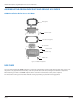
ORION® Gas Endpoints, Integral Endpoint for Sensus® 415 Gas Meters ASSEMBLE THE ORION ENDPOINT AND SENSUS 415 INDEX ORION Installation Kit for Sensus 415 Meter Meter gasket 10-24 x 1” screws Lens (outer cover) gasket #6 x 3/4” screws #8 x 1/2” screws Lens (outer cover) Tamper Seals Figure 5: Installation kit parts list USE CARE Use care when handling the ORION endpoint to ensure the endpoint drive pawls and the mating index drive gear are not subjected to any physical abuse.
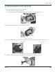
Installation Manual PLACE THE ENDPOINT ONTO THE METER 1. Place the endpoint gasket on the rear of the endpoint. a. Place the two slots through the guide pins. b. Place the gasket so that the rounded part goes under the endpoint rear drive shaft. See Figure 6. Figure 6: Placement of gasket on rear of endpoint 2. Place three (3) screws (10-24 X 1") into the endpoint. See Figure 7. Screws Figure 7: Screw placement 3.
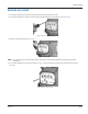
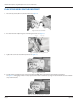
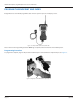
ORION® Gas Endpoints, Integral Endpoint for Sensus® 415 Gas Meters PLACE THE INDEX ON THE ENDPOINT 1. Place two (2) screws (#6 X ¾") into the index. See Figure 10. Figure 10: Place screws in index 2. Be certain that the endpoint gears and index gears mesh. See Figure 11. Index gears Endpoint gears Figure 11: Endpoint and index gears mesh 3. Tighten the screws to about 4 inch-pounds. See Figure 12. Figure 12: Tighten index screws 4. Test the index and endpoint gear connection.
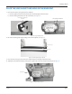
Installation Manual PLACE THE LENS GASKET AND LENS ON THE ENDPOINT 1. Place the lens (outer cover) gasket on the endpoint. a. Place the gasket so that its notched hole goes around the upper left screw hole. b. Place the other gasket holes over the screw holes. See Figure 14. Notched hole around upper left screw Lens gasket on endpoint Figure 14: Lens gasket placement 2. Be certain that the gasket stepped edge seats in the endpoint. See Figure 15.
ORION® Gas Endpoints, Integral Endpoint for Sensus® 415 Gas Meters PROGRAM THE ENDPOINT AND INDEX Badger Meter uses a handheld programmer/data collector system to process and display screens. Figure 17: Sample handheld, IR read head and cable Please reference the Programming Guide for ORION gas endpoints and the manual for the handheld system. Programming Procedure To program the endpoint, align the IR port of the handheld optic read head with the endpoint IR port. See Figure 18.
Installation Manual INSERT TAMPER PLUGS After programming the endpoint is complete and for security purposes, insert the four (4) red tamper plugs (supplied) into the screw holes and push them in until flush. See Figure 19. Tamper plugs Figure 19: Tamper plug placement INSTALLATION IS COMPLETE Installation of the ORION endpoint for a SENSUS 415 gas meter with dial index is now complete.
Making Water Visible® MAKING WATER VISIBLE and ORION are registered trademarks of Badger Meter, Inc. Other trademarks appearing in this document are the property of their respective entities. Due to continuous research, product improvements and enhancements, Badger Meter reserves the right to change product or system specifications without notice, except to the extent an outstanding contractual obligation exists. © 2014 Badger Meter, Inc. All rights reserved. www.badgermeter.