
Hardware Solutions for Gas Utilities Instruction Manual
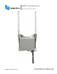


Installation Manual
Tools and Materials (Customer-supplied)
• Phillips #2 screwdriver
• Precision slotted screwdriver with a 2.0 millimeter (0.079 inch) blade size
• Two 9/16 inch or adjustable wrenches for mounting V-block clamps (standard mounting)
• BAND-IT® tool (see "Banding Mounting" on page 15) and instructions, a 1/2 inch wrench and a hammer for large
diameter pole mounting
• Wrench (for 1-1/16 inch gland nut and 1-1/16 inch dome nut)
• Pliers or strap wrench (for tightening the 15/16 inch OD backhaul antenna and other Type N connectors)
• 7/16 inch socket wrench for all other bolts and nuts
• Cat5e Ethernet cable (outdoor-rated) and RJ45 jack for LAN connection
Connect the Battery Backup
MPORTANTI
The gateway contains an onboard battery backup. The battery must be connected before the gateway is installed and
powered. Follow these steps to connect the battery backup.
OTE:N See "Battery Backup Replacement" on page 32 for details on replacing the battery.
1. Using a #2 slotted or Phillips screwdriver, remove the
enclosure cover by unscrewing the four corner-cover
screws.
OTE:N The battery is held in place by the enclosure
cover only. No other adhesive or locking
mechanism is used.
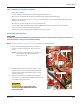
2. Carefully install the battery connector onto the circuit
board. Insert the connector only far enough so that the
connector latch engages. Verify that proper connector
polarity is observed.
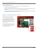
3. Replace the enclosure cover. Tighten each of the four
cover screws to 16 inch-pounds, maximum. Be careful not
to overtighten any of the screws.
BE CAREFUL NOT TO CRIMP THE BATTERY
CONNECTOR CABLE WHEN REPLACING THE
ENCLOSURE COVER.
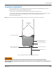
Figure 2: Battery connection
Battery Connector
Battery Connection
Page 9 March 2014