
Hardware Solutions for Gas Utilities Instruction Manual


Installation Manual
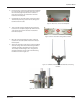
15. Connect the AC-to-DC power supply to the gateway power cable using the attached 308 connector and verify the
LED indicator on the bottom of the enclosure is on with a steady green light as shown in Figure 55.
OTE:N A red blinking light indicates the gateway is being powered by the internal backup battery.
No light indicates the gateway is not receiving power.
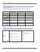
Figure 55: Powered gateway
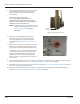
Figure 56: Gateway on battery backup
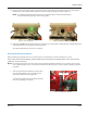
16. Complete the ORION Fixed Network II Gateway Installation Form and send the completed form to Badger Meter with
any attachments. The three-page form starts on page 43.
The remote TX/RX antenna connection is complete.
Remote Backhaul Antenna Installation
Before installing the backhaul antenna in a remote location, first determine if a remote installation is needed.
In the location selected for the gateway, test the backhaul connection while the backhaul antenna is still connected to the
gateway by doing the following.
OTE:N For testing the backhaul connection, make sure the gateway ReadCenter® Monitor server is running, the enclosure
cover is o the gateway so the circuit board is visible, the backhaul antenna is connected to the gateway and power
is available.
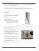
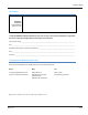
1. Turn on the gateway power. On the circuit board in
the lower left quadrant, next to the SIM card slot,
look for the LED labeled ”TCP“ (Figure 57).
The TCP LED will light when the backhaul links with
the server, signifying a connection.
Figure 57: Backhaul antenna LED
”TCP“ LED
Page 41 March 2014