
Hardware Solutions for Gas Utilities Instruction Manual


ORION® Fixed Network (SE) II Network Gateway Transceiver
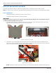
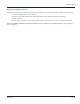
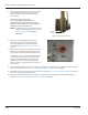
9. Prepare each of the antenna cables and connectors
per manufacturer’s instructions and connect to
the Type N female connector at the bottom of
each antenna.
Tighten each Type N connector to
8…12 inch-pounds. To approximate this
measurement without a torque wrench, nger
tighten the Type N connector and then tighten an
additional 1/16 inch turn with pliers.
OTE:N A lightning arrestor is recommended for all
remote antenna installations. See "Lightning
Arrestors" on page 26 for additional
information.
Figure 53: Type N female connector
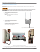
10. Collect the required VSWR readings after the
antennas are installed in their nal locations.
Record the information on the form provided
by Badger Meter. See "Required Antenna Tests" on
page 36.
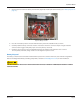
11. After the antenna tests are completed, connect the
TX/RX antenna to the Type N female connector on
the gateway enclosure (marked ”TX/RX Antenna’’).
The antenna cable can be connected directly to the
enclosure. If needed, a 3-foot coaxial cable with
Type N straight standard male plugs, both ends,
(67628-001) can be used to transition from the
antenna connector to Type N female connector on
the enclosure.
Figure 54: TX/RX Antenna connector
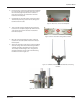
12. Loosen the four (4) captive screws on the gateway enclosure cover. Remove the cover, attach the internal backup
battery and reattach the cover. See "Connect the Battery Backup" on page 9 if you need help.
13. Wire the M12 connector according to the instructions provided ("M12 Connector Assembly" on page 23) and attach
the power cable to the gateway enclosure.
14. Mount the backplate and the gateway enclosure using V-block mounting hardware or Band-IT banding kit as
appropriate. See "Using V-block Mounting Clamps" on page 14 for details.
Type N Female
Connector
Page 40 March 2014