
Hardware Solutions for Gas Utilities Instruction Manual


Installation Manual
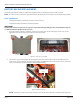
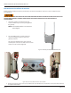
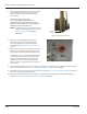
4. Disconnect the enclosure bracket from the backplate
by removing the two (2) locknuts from each side of
the enclosure (Figure 49). Retain the locknuts as
they will be used later to reattach the enclosure
bracket to the backplate.
5. Carefully lift the enclosure (with enclosure bracket)
o the backplate using caution to not damage the
backhaul antenna cable.
Figure 49: Disconnect enclosure from backplate
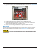
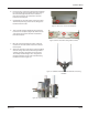
6. Three locknuts hold the TX/RX antenna mounting
bracket on the backplate (Figure 50). Remove those
and separate the antenna bracket and antennas
from the backplate.
Figure 50: Remove antenna mounting bracket locknuts
7. Once the antenna mounting bracket is removed,
reattach the enclosure (with enclosure bracket) to
the backplate.
8. Attach the antenna bracket to the remote mounting
structure using either V-block mounting hardware
or Band-IT banding, depending on the structure.
The example shown in Figure 51 is using V-block
mounting hardware. A side view of the mounting
hardware is shown in Figure 52.
Figure 51: TX/RX antenna bracket attached with V-block mounting
hardware
Figure 52: V-block mounting hardware side view
Page 39 March 2014