
Hardware Solutions for Gas Utilities Instruction Manual


Installation Manual
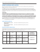
Assembly Size, Weight, Wind Loading
See "Specifications" on page 6 for the complete specifications list.
Height Width Depth Weight Wind
Loading
Area
Direct Mount
Antennas
Assembly
(includes gateway enclosure,
TX/RX antennas, backhaul antenna and
mounting brackets)
43.8" 15.5" 6.5" 23.2 lb 1.5 ft
2
Remote Mount
Antennas
Gateway enclosure with mounting bracket 10.3" 14.5" 6.5" 17.5 lb 1.0 ft
2
TX/RX antennas with mounting bracket 21.3" 15.5" 2.9" 4.8 lb 0.8 ft
2
Backhaul antenna with mounting bracket 16.6" 4.2" 2.1" 0.9 lb 0.2 ft
2
Mounting Hardware
V-Block mounting kit 1.6 lb
Banding mounting kit 1.0 lb
Weatherproofing for Connector/Cable Connections
Weatherproofing material should be provided by the installation contractor. Badger Meter recommends weatherproofing
for all connections according to cable and connector manufacturer recommendations. Weatherproofing provides additional
moisture protection and will prevent the connections from loosening due to vibrations.
MPORTANTI
All external antennas are designed with vent holes. Any weatherproofing applied to the Type N connectors must not
obstruct this venting or the antenna can be damaged.
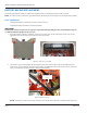
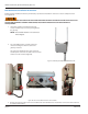
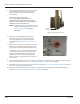
• On the TX/RX antennas, small vent
holes are located at the bottom end of
the antenna, next to the Type N female
connector as shown in Figure 45.
Figure 45: Vent holes at bottom of TX/RX antenna
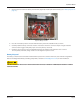
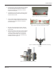
• On the backhaul antenna, the vent holes
are located at each end (Figure 46). At
the bottom end with the Type N male
connector, the vent holes are on the
outside, on the metal section. At the top,
the holes are incorporated into the cap.
Figure 46: Vent holes at bottom and top of backhaul antenna
Vent Holes
Vent Hole
Vent Hole
Vent Hole
Page 35 March 2014