
Hardware Solutions for Gas Utilities Instruction Manual


Installation Manual
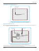
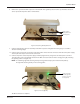
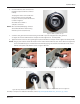
8. Remove the cap from the M12 receptacle on the bottom of the gateway transceiver. The cap should be saved so it
can be replaced if the power cable is removed later.
Figure 25: Bottom of gateway transceiver
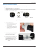
9. Connect the M12 plug connector assembly to the M12 receptacle and tighten the locking ring in a clockwise
direction until nger tight.
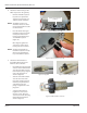
10. Connect the 308 connector on the other end of the power cable to the 308 connector of the AC-to-DC power supply
and snap the anti-tamper collar over the connection.
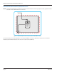
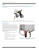
11. Connect the power cord to the power supply and then plug the three-prong male end of the power cord into a
120V AC power source. The LED indicator above the M12 connection turns on with a steady green light, indicating
the gateway power is on (Figure 26).
OTE:N A red blinking light indicates the gateway is being powered only by the internal backup battery.
No light indicates the gateway is not receiving power.
Figure 26: Powered gateway
The M12 connection is complete.
M12 Receptacle
with Cap Removed
RJ45 Receptacle
Steady green light
indicates gateway
power is on (not on
backup power)
Page 25 March 2014