
Hardware Solutions for Gas Utilities Instruction Manual


ORION® Fixed Network (SE) II Network Gateway Transceiver
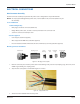
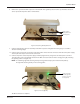
4. Strip the ends of the six (6) colored wires to a length of 1/8 inch. Twist the conductors on each wire.
5. Shorten the drain/bare wire (no insulation) to 11/16 inch.
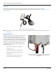
6. Loosen each screw (about 2…3 turns) on the female insert and attach the wires to the female insert using the chart
below. Retighten each screw after the wire has been connected.
BE CAREFUL NOT TO BACK THE SCREWS OUT TOO FAR. THE SCREWS ARE SMALL AND CAN EASILY BE LOST IF THEY
ARE DROPPED.
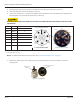
Function Wire Female insert connector
Female Insert Diagram - Top View
Female Insert Photo - Top View
V DC+ Red 1
V DC– Brown 2
V DC– Black 3
RS232 White* 4
RS232 Green* 5
Not used Not
used
6
V DC+ Blue 7
V DC– Drain** 8 (Center)
* Used with the serial programming harness (66529-002)
** Used with shielded cable only
OTE:N For additional information about DC power source, see "Absolute Requirements" on page 20.
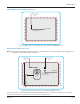
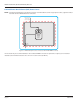
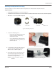
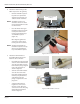
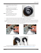
7. Assemble the female insert to the coupling sleeve by aligning the female insert tab slot with the notch in the
coupling sleeve.
Figure 24: Slot alignment
Female Insert
Tab Slot
Coupling Sleeve Insert
Notch
Slot
Brown
Red
Black
Blue
White
Not
Used
Green
Drain
Page 24 March 2014