
Hardware Solutions for Gas Utilities Instruction Manual
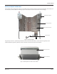

ORION® Fixed Network (SE) II Network Gateway Transceiver
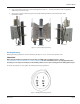
Mounting Bracket
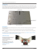
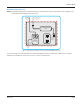
The mounting bracket is machined with multiple holes to accommodate different mounting options. Mounting holes and the
V-Block, banding and wall mounting options are labeled on the bracket. The bracket also has 1/4 inch and 3/8 inch grounding
points (see Figure 6) which can be used if needed. When shipped, the mounting bracket, TX/RX antenna bracket and backhaul
antenna bracket are attached. Together they make up the backplate which is attached to the gateway enclosure bracket.
Figure 6: Mounting bracket
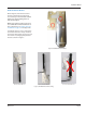
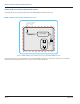
Mounting Options
The circular hole pattern on the mounting bracket can be used to accommodate mounting the gateway on an angled beam
or pole, if necessary.
The gateway can also be mounted on a wall. The mounting bracket has four 0.28 inch holes marked for this option.
OTE:N For a wall mount, customers must supply mounting hardware suitable for the substructure on which the gateway
is mounted.
For mounting options, all gateway installation considerations must be observed. See "Specifications" on page 6, "Mounting
the Gateway" on page 8 and "Remote Antenna Installation" on page 34.
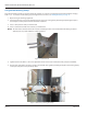
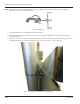
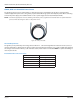
TX/RX Antenna Bracket
When shipped, the TX/RX antenna bracket
is mounted to the top of the mounting
bracket with three locknuts
(67810-001). The mounting holes are
indicated in Figure 7.
Other holes on the bracket can be used
to accommodate remote installation. For
more information, see "Remote Antenna
Installation" on page 34 in
the Appendix.
Figure 7: TX/RX antenna bracket
Used to Mount Backhaul
Antenna Bracket
Used to Mount TX/RX
Antenna Bracket
Grounding Points
Page 12 March 2014