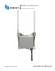
ORION® Fixed Network II Network Gateway Transceiver ORI-UM-00205-EN-02 (March 2014) Installation Manual
ORION® Fixed Network (SE) II Network Gateway Transceiver Page ii March 2014
Installation Manual CONTENTS OVERVIEW . . . . . . . . . . . . . . . . . . . . . . . . . . . . . . . . . . . . . . . . . . . . . . . . . . . . . . . . . . . . 5 Product Description . . . . . . . . . . . . . . . . . . . . . . . . . . . . . . . . . . . . . . . . . . . . . . . . . . . . 5 License Requirements . . . . . . . . . . . . . . . . . . . . . . . . . . . . . . .
ORION® Fixed Network (SE) II Network Gateway Transceiver Page iv March 2014
Installation Manual OVERVIEW This manual contains installation instructions for the ORION® Fixed Network (SE) II network gateway transceiver. Proper performance and reliability of the gateway depends upon installation in accordance with these instructions. NNOTE: Refer to the Gateway Configuration Software manual available at www.badgermeter.com for instructions on configuring and programming the gateway.
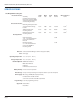
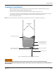
ORION® Fixed Network (SE) II Network Gateway Transceiver SPECIFICATIONS Size/Weight/Wind Loading Area Height Width Depth Weight Wind Loading Area 43.8" 15.5" 6.5" 23.2 lb 1.5 ft2 Network gateway transceiver enclosure with mounting bracket 10.3" 14.5" 6.5" 17.5 lb 1.0 ft2 TX/RX antennas with mounting bracket 21.3" 15.5" 2.9" 4.8 lb 0.8 ft2 Backhaul antenna with mounting bracket 16.6" 4.2" 2.1" 0.9 lb 0.
Installation Manual STANDARD COMPONENTS • One (1) gateway transceiver assembly with attached mounting backplate and TX/RX fiberglass antennas • One (1) backhaul antenna (CDMA or GPRS gateway units) • V-block clamps or banding and locking equipment for attaching the gateway to a pole • 100-foot or 300-foot power cable, M12 plug (not included with LAN configuration if Ethernet (PoE) is used for power), RJ45 plug assembly for LAN configuration, AC-to-DC power supply and power cord • Extra locknuts (r
ORION® Fixed Network (SE) II Network Gateway Transceiver MOUNTING THE GATEWAY IIMPORTAN Professional installation of the ORION Fixed Network II network gateway transceiver per Badger Meter installation instructions is required. Installation, mounting and disposal shall be in accordance with all local, state and federal regulations.
Installation Manual Tools and Materials (Customer-supplied) • Phillips #2 screwdriver • Precision slotted screwdriver with a 2.0 millimeter (0.
ORION® Fixed Network (SE) II Network Gateway Transceiver Attach the Backhaul Antenna 1. Remove the plastic cover from the Type N female connector on the backhaul antenna bracket. 2. Remove the backhaul antenna from the carton. 3. Thread the Type N male connector (antenna) onto the Type N female connector on the backhaul antenna bracket. NNOTE: See "Backhaul Antenna Bracket" on page 13 for additional mounting information. 4. Hand tighten until finger tight.
Installation Manual Gateway Backplate with Brackets The backplate of the gateway transceiver has a modular design consisting of three brackets joined together. The brackets can be removed to provide additional mounting options. A description of each bracket starts on the next page.
ORION® Fixed Network (SE) II Network Gateway Transceiver Mounting Bracket The mounting bracket is machined with multiple holes to accommodate different mounting options. Mounting holes and the V-Block, banding and wall mounting options are labeled on the bracket. The bracket also has 1/4 inch and 3/8 inch grounding points (see Figure 6) which can be used if needed. When shipped, the mounting bracket, TX/RX antenna bracket and backhaul antenna bracket are attached.
Installation Manual Backhaul Antenna Bracket When shipped, the backhaul antenna bracket is mounted to the bottom of the mounting bracket with two locknuts (67810-001). The mounting holes are indicated in Figure 8. Other holes on the bracket can be used to accommodate remote installation. For more information, see "Remote Antenna Installation" on page 34 in the Appendix. A backhaul antenna can be connected to the bracket with either end up.
ORION® Fixed Network (SE) II Network Gateway Transceiver Using V-block Mounting Clamps The V-block mounting clamps are sized to mount the gateway on a vertical or horizontal pole with outer diameters ranging from 1-1/4… 2-1/2 inches. For mounting on poles larger than 2-1/2 inches, see "Banding Mounting" on page 15. 1. Open the bag of mounting equipment. 2. Place two bolts (3/8-16 x 5 inches) through the holes in the top of the gateway mounting backplate (Figure 10).
Installation Manual 7. Place a lock washer and nut on each bolt and tighten the nuts 100…150 inch-pounds to ensure the gateway is sufficiently secured to the pole. 8. Repeat Steps 7 and 8 for attaching the V-block clamp mounting hardware to the bottom bolts of the mounting backplate. Side View Back View Side View Figure 12: Completed gateway mounting Banding Mounting Banding mounting equipment is sized to mount the gateway on a 2-1/2…24-inch outer diameter pole.
ORION® Fixed Network (SE) II Network Gateway Transceiver NNOTE: Installation of banding mounting requires the use of the BAND-IT tool shown below (66042-006) or equivalent BAND-IT tool as recommended by BAND-IT. Figure 14: BAND-IT tool 1. Locate the BAND-IT tool and supplied installation instructions. 2. Follow the BAND-IT-supplied installation instructions enclosed with the BAND-IT tool for attaching the gateway transceiver to a pole. 3.
Installation Manual POWER SOURCE CONFIGURATIONS Access to Power • The gateway transceiver requires access to power. The gateway can use a 120V AC grounded outlet for use with the AC-to-DC power supply and power cord (66528-003), or a DC power source for use with the DC power source cable with 308 in-line connector (66233-020). For a gateway with a LAN PoE configuration, a Power over Ethernet connection is required. Diagrams of each power source configuration start on page 18.
ORION® Fixed Network (SE) II Network Gateway Transceiver CDMA, GPRS or LAN with 120V AC Power Source Configurations for a 120V AC grounded outlet with CDMA, GPRS and LAN are shown here.
Installation Manual LAN with 120V AC Power Source NNOTE: Consult the manufacturer's installation and usage recommendations as well as appropriate codes, regulations and standards for the LAN RJ45 Ethernet connection.
ORION® Fixed Network (SE) II Network Gateway Transceiver CDMA, GPRS or LAN with DC Power Source The gateway transceiver can be ordered with a 10-foot DC power source cable (66233-020) for direct connection with a customer-supplied DC power source. The gateway requires about 6W average power and 12W peak power. When connecting an AC-to-DC power supply, the recommendation is to use a power supply rated at 1A (minimum) at 24V DC.
Installation Manual CDMA or GPRS Connection with DC Power Source ORION SE Power Cable with 308 In-line Connector (supplied) 10-foot DC Power Source Cable with 308 In-line Connector End (supplied) DC Power Source (customer supplied) Figure 19: CDMA or GPRS connection with DC power source (*Shown with NEMA 4 enclosure) LAN Connection with DC Power Source NNOTE: Consult the manufacturer's installation and usage recommendations as well as appropriate codes, regulations and standards for the LAN RJ45 Ethern
ORION® Fixed Network (SE) II Network Gateway Transceiver LAN with Power Over Ethernet (PoE) Power Source NNOTE: Consult the manufacturer's installation and usage recommendations as well as appropriate codes, regulations and/or standards for the LAN RJ45 Ethernet connection.
Installation Manual ELECTRICAL CONNECTIONS M12 Connector Assembly The M12 connector assembly is required for all power source configurations except LAN with PoE. NNOTE: Use only approved Badger Meter power cable, 100-foot (66233-015) or 300-foot (66233-017), for this assembly.
ORION® Fixed Network (SE) II Network Gateway Transceiver 4. Strip the ends of the six (6) colored wires to a length of 1/8 inch. Twist the conductors on each wire. 5. Shorten the drain/bare wire (no insulation) to 11/16 inch. 6. Loosen each screw (about 2…3 turns) on the female insert and attach the wires to the female insert using the chart below. Retighten each screw after the wire has been connected. BE CAREFUL NOT TO BACK THE SCREWS OUT TOO FAR.
Installation Manual 8. Remove the cap from the M12 receptacle on the bottom of the gateway transceiver. The cap should be saved so it can be replaced if the power cable is removed later. M12 Receptacle with Cap Removed RJ45 Receptacle Figure 25: Bottom of gateway transceiver 9. Connect the M12 plug connector assembly to the M12 receptacle and tighten the locking ring in a clockwise direction until finger tight. 10.
ORION® Fixed Network (SE) II Network Gateway Transceiver AC Power Badger Meter provides an Emerson AC-to-DC power supply with cord (66528-003) that plugs into a standard three-prong 120V AC outlet. If you are powering the gateway directly via DC power, see "CDMA, GPRS or LAN with DC Power Source" on page 20. Figure 27: 120V AC power supply with power cord NNOTE: If you replace a gateway, make sure to replace the power supply cord with the Emerson power supply cord at the same time.
Installation Manual RJ45 Plug Assembly for LAN Connectivity Use this procedure to connect an Ethernet cable to the gateway for a LAN backhaul or any PoE connection.
ORION® Fixed Network (SE) II Network Gateway Transceiver 4. Attach the metal housing to the RJ45 receptacle on the gateway: • Remove the RJ45 receptacle bayonet lock cap from the gateway by turning the cap 1/4 turn counter clockwise. RJ45 Receptacle Bayonet Lock Cap NNOTE: The RJ45 receptacle cap should be saved so it can be replaced if the Ethernet cable is removed later.
Installation Manual 6. Insert the Ethernet cable connector into the RJ45 receptacle. Push the connector in firmly. The plug latch of the connector fits into the recessed key section of the RJ45 receptacle. A close-up view from the front is shown in Figure 37. An audible click confirms a complete connection. NNOTE: Once assembled, RJ45 plugs cannot be disassembled from the metal housing without a special tool (67163-001). Figure 37: RJ45 receptacle close up 7.
ORION® Fixed Network (SE) II Network Gateway Transceiver DUAL BACKHAUL CONFIGURATION ORION Fixed Network II network gateway transceivers are configured to allow a dual backhaul connection so you can switch from CDMA (or GPRS) to an alternative LAN backhaul, if necessary, using the RJ45 plug assembly included with the transceiver. The CDMA (or GPRS) connection can remain in place when the LAN connection is set up. See "LAN with 120V AC Power Source" on page 19 for the LAN installation diagram.
Installation Manual APPENDIX March 2014 Page 31
ORION® Fixed Network (SE) II Network Gateway Transceiver BATTERY BACKUP REPLACEMENT If a battery replacement is required, complete the installation steps as detailed below in the order presented. NNOTE: It is not necessary to disconnect AC power from the gateway before removing the cover and replacing the battery.
Installation Manual 3. Grasp and pull to remove the battery from the unit (Figure 44) and safely discard the battery (see "Battery Disposal" on page 33). Figure 44: Battery removal 4. Place the new battery into the enclosure with the battery label “This Side Out” visible, as shown. 5. Carefully install the battery connector onto the circuit board. Insert the connector only far enough so that the connector latch engages. Verify that proper connector polarity is observed. 6.
ORION® Fixed Network (SE) II Network Gateway Transceiver REMOTE ANTENNA INSTALLATION This section provides instructions for installing the TX/RX antennas and/or the backhaul antenna separately from the ORION Fixed Network II network gateway transceiver. The ORION Fixed Network II network gateway transceiver (“gateway”) is designed to allow remote antenna mounting.
Installation Manual Assembly Size, Weight, Wind Loading See "Specifications" on page 6 for the complete specifications list. Direct Mount Assembly Antennas (includes gateway enclosure, TX/RX antennas, backhaul antenna and mounting brackets) Remote Mount Antennas Gateway enclosure with mounting bracket TX/RX antennas with mounting bracket Backhaul antenna with mounting bracket Mounting Hardware V-Block mounting kit Banding mounting kit Height Width Depth Weight 43.8" 15.5" 6.5" 23.
ORION® Fixed Network (SE) II Network Gateway Transceiver Installation Considerations To help maximize the performance of the ORION fixed network system, the following installation guidelines and recommendations should be considered when selecting mounting locations for gateways. The utility is responsible for properly positioning the gateway. For optimal reception and transmission, locate the gateway transceiver and antennas in line-of-sight view of the desired endpoints.
Installation Manual Required Installation Pictures The installation contractor is required to provide electronic images of each gateway installation to Badger Meter as follows.
ORION® Fixed Network (SE) II Network Gateway Transceiver Remote Antenna Installation Instructions Remote antenna installations must be performed by a professional installation contractor to ensure compliance with FCC regulations. FAILURE TO READ AND FOLLOW THE INSTRUCTIONS PROVIDED CAN LEAD TO MISAPPLICATION OR MISUSE OF THE ORION FIXED NETWORK II GATEWAY TRANSCEIVER, RESULTING IN PERSONAL INJURY AND DAMAGE TO THE EQUIPMENT. 1. Unpack the gateway assembly from the box.
Installation Manual 4. Disconnect the enclosure bracket from the backplate by removing the two (2) locknuts from each side of the enclosure (Figure 49). Retain the locknuts as they will be used later to reattach the enclosure bracket to the backplate. 5. Carefully lift the enclosure (with enclosure bracket) off the backplate using caution to not damage the backhaul antenna cable. Figure 49: Disconnect enclosure from backplate 6.
ORION® Fixed Network (SE) II Network Gateway Transceiver 9. Prepare each of the antenna cables and connectors per manufacturer’s instructions and connect to the Type N female connector at the bottom of each antenna. Tighten each Type N connector to 8…12 inch-pounds. To approximate this measurement without a torque wrench, finger tighten the Type N connector and then tighten an additional 1/16 inch turn with pliers. NNOTE: A lightning arrestor is recommended for all remote antenna installations.
Installation Manual 15. Connect the AC-to-DC power supply to the gateway power cable using the attached 308 connector and verify the LED indicator on the bottom of the enclosure is on with a steady green light as shown in Figure 55. NNOTE: A red blinking light indicates the gateway is being powered by the internal backup battery. No light indicates the gateway is not receiving power. Figure 55: Powered gateway Figure 56: Gateway on battery backup 16.
ORION® Fixed Network (SE) II Network Gateway Transceiver 2. If there is a connection, the backhaul antenna bracket and antenna can remain connected to the gateway. Remote installation is not required for the backhaul antenna. If there is no connection, remove the backhaul antenna bracket from the gateway. There are two locknuts holding the backhaul antenna mounting bracket on the backplate. Remove those to separate the antenna bracket and backhaul antenna from the backplate. 3.
Installation Manual ORION® Fixed Network II Gateway Installation Form Instructions: Complete a separate form for each gateway installation. Return completed form(s) and attachments according to the instructions on the last page of the form. If you have questions about this form, contact Badger Meter Technical Support, TechSupport@BadgerMeter.com or call 800-876-3837. ORION Fixed Network Gateway Transceiver Information All installations – Complete table below.
ORION® Fixed Network (SE) II Network Gateway Transceiver Cables & Connectors Remote antenna installations only – Antenna cables and connectors are not included and are to be supplied by the professional installation contractor. Exact parts specified in Badger Meter installation documentation must be used. Substitutions are not allowed. Confirm parts used by completing table below.
Installation Manual Comments Installation Comments Attach additional pages as needed I certify the ORION Fixed Network II Gateway Transceiver and any remote antenna installations, if applicable, have been completed per Badger Meter documentation and instructions.
ORION® Fixed Network (SE) II Network Gateway Transceiver Page 46 March 2014
Installation Manual INTENTIONAL BLANK PAGE March 2014 Page 47
Making Water Visible® ORION and ReadCenter are registered trademarks of Badger Meter, Inc. Other trademarks appearing in this document are the property of their respective entities. Due to continuous research, product improvements and enhancements, Badger Meter reserves the right to change product or system specifications without notice, except to the extent an outstanding contractual obligation exists. © 2014 Badger Meter, Inc. All rights reserved. www.badgermeter.