ORION® Gas Endpoints Integral Endpoint for Itron®/Actaris® Straight-Face Gas Meters ORI-UM-00905-EN-03 (July 2014) Installation Manual
ORION® Gas Endpoints, Integral Endpoint for Itron®/Actaris® Straight-Face Gas Meters Page ii July 2014
Installation Manual CONTENTS Disclaimer . . . . . . . . . . . . . . . . . . . . . . . . . . . . . . . . . . . . . . . . . . . . . . . . . . . . . . . . . . . . . . . . . . . . . . . . . . .5 Questions Or Service Assistance . . . . . . . . . . . . . . . . . . . . . . . . . . . . . . . . . . . . . . . . . . . . . . . . . . . . . . . . . . . . .5 Product Identification . . .
ORION® Gas Endpoints, Integral Endpoint for Itron®/Actaris® Straight-Face Gas Meters Page iv July 2014
Installation Manual DISCLAIMER The user/purchaser is expected to read and understand the information provided in this manual, follow any listed safety precautions and instructions and keep this manual with the equipment for future reference. Misuse, mishandling and/or inadequate maintenance may impair performance and/or compromise safety. QUESTIONS OR SERVICE ASSISTANCE If you have questions regarding the product or this document contact: Badger Meter, Inc. P.O.
ORION® Gas Endpoints, Integral Endpoint for Itron®/Actaris® Straight-Face Gas Meters LICENSE REQUIREMENTS This device complies with Part 15 of FCC Rules. Operation of this device is subject to the following conditions: (1) This device may not cause harmful interference and (2) this device must accept any interference received, including interference that may cause undesired operation.
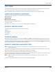
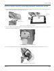
Installation Manual ITRON/ACTARIS STRAIGHT-FACE MODELS 175/250/400 Remove Old Index 1. Use a screwdriver to puncture and remove the tamper plugs, if present. 2. Use a Phillips screwdriver to remove and discard the four (4) mounting screws and the cover. See Figure 1. Figure 1: Unscrew mounting screws 3. Remove and discard the index. The straight-face index will be replaced by a slant-face index included in the installation kit. See Figure 2.
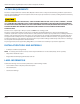
ORION® Gas Endpoints, Integral Endpoint for Itron®/Actaris® Straight-Face Gas Meters ORION MATERIALS FOR ITRON/ACTARIS STRAIGHT-FACE METER Endpoint gasket Adapter 4 Screws 1/4-20 x 1/2” Housing gasket 3 Screws 8-16 x 1/2” ORION endpoint 2 Screws 8-16 x 1/2” Slant-face index Cover gasket 4 Screws 8-16 x 1/2” Cover 4 Tamper plugs Figure 4: Parts USE CARE Use care when handling the ORION endpoint to ensure the endpoint drive pawls and the mating index drive gear are not subjected to any physical abus
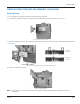
Installation Manual INSTALL ORION GASKETS, ADAPTER, ENDPOINT, INDEX AND COVER 1. Begin installation by placing a new meter gasket on the adapter. Remove the protective paper, line-up the four holes and stick the gasket on the flat side of the adapter. See Figure 5. Meter gasket on flat side of adapter Protective paper Figure 5: Remove protective paper from meter gasket 2. Place the adapter with the gasket onto the meter housing with four (4) ¼-20 x ½" supplied screws. See Figure 6.
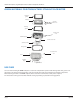
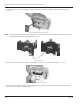
ORION® Gas Endpoints, Integral Endpoint for Itron®/Actaris® Straight-Face Gas Meters 4. Install two (2) 8-16 x ½" index mounting screws part way into the front of the endpoint. They will be tightened later. See Figure 8. Figure 8: Intallation of index mounting screws NNOTE: Care must be taken when placing the index units on an endpoint. The front drive pawls must mate without causing any binding or potential for disengagement. See Figure 9. Drive pawls Figure 9: Drive pawls 5.
Installation Manual Index, endpoint, gasket assembly Post Adapter Figure 11: Placement of housing gasket assembly on adapter 7. Be sure the gas meter drive pawl mates with the slot in the endpoint drive shaft. These components must mate without causing any binding or potential for disengagement. See Figure 12and Figure 13.
ORION® Gas Endpoints, Integral Endpoint for Itron®/Actaris® Straight-Face Gas Meters NNOTE: Use care when handling the ORION endpoint to ensure the drive shaft is not subjected to any physical abuse. Abuse may cause this spindle to become bent, misaligned or otherwise inoperative. 8. Attach this assembly onto the meter with three (3) 8-16 x ½" screws. See Figure 14. Tighten screws to 15 inch-pounds maximum. Figure 14: Attach assembly onto meter 9. Place the cover gasket on the endpoint.
Installation Manual 10. Slip the ORION cover over the outside of the index and endpoint. With four (4) 8-16 x ½" screws attach the cover to the meter. See Figure 16. Tighten screws to 15 inch-pounds maximum.
ORION® Gas Endpoints, Integral Endpoint for Itron®/Actaris® Straight-Face Gas Meters PROGRAM THE ENDPOINT AND INDEX Badger Meter uses a handheld programmer/data collector system to process and display screens. Figure 17: Sample handheld, IR read head and cable Please reference the Programming Guide for ORION gas endpoints and the manual for the handheld system. Programming Procedure To program the endpoint, align the IR port of the handheld optic read head with the endpoint IR port. See Figure 18.
Installation Manual INSERT TAMPER PLUGS After programming the endpoint is complete and for security purposes, insert the four (4) red tamper plugs (supplied) into the screw holes and push them in until flush. See Figure 19. Tamper plugs Figure 19: Tamper plugs INSTALLATION IS COMPLETE Installation of the ORION endpoint on an Itron/Actaris Straight-Face models 175/250/400 with odometer index is now complete.
Making Water Visible® MAKING WATER VISIBLE and ORION are registered trademarks of Badger Meter, Inc. Other trademarks appearing in this document are the property of their respective entities. Due to continuous research, product improvements and enhancements, Badger Meter reserves the right to change product or system specifications without notice, except to the extent an outstanding contractual obligation exists. © 2014 Badger Meter, Inc. All rights reserved. www.badgermeter.