
Hardware Solutions for Gas Utilities User guide


Installation Manual
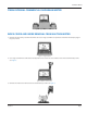
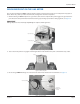
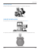
4. Place the index drive pawl perpendicular to the shaft adapter. See Figure 20.
Index drive pawl
Shaft adapter
Figure 20: Index drive pawl placement
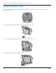
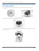
5. Be certain the index tab holes remain engaged with the locating posts.
6. Be sure the adapter plate alignment bushings engage the holes in the endpoint unit. See Figure 21.
7. Verify all pawls align. Turn the 2.5 feet wheel. It should move just a little.
Alignment bushings
engaging holes in
endpoints
Figure 21: Verify pawls align
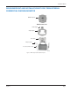
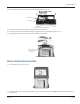
INDEX COVER OVER THE INDEX
1. Place the index cover over the index.
Figure 22: Index cover placement
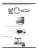
2. Use the four (4) ¼-20 X 3 3/8" supplied mounting screws to attach the index to the ORION endpoint and the endpoint to
the gas meter.
Page 13 July 2014