
User Manual
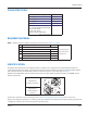
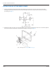
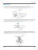
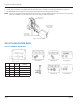
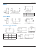
Table Of Contents
WIRING GASRT
1. Feed the two-conductor shielded transmitter wires (Belden 9802) through the hole in the housing.
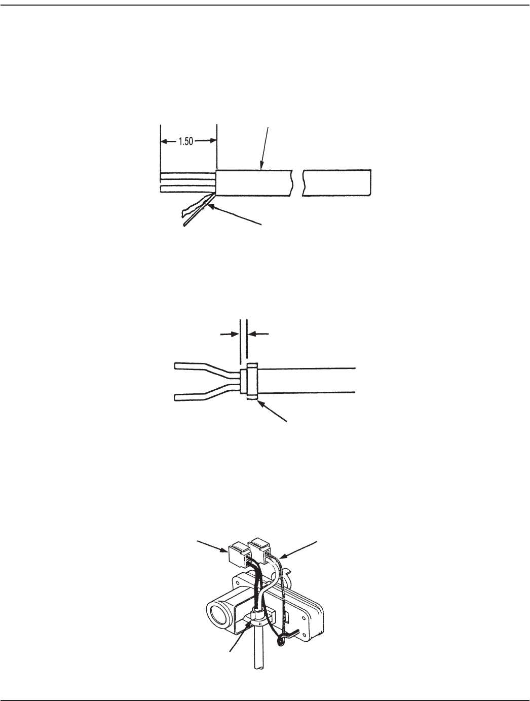
2. Strip approximately 1-1/2 inch of outer insulation sheath from the cable using the 59989-001 Coax Stripping Tool. Use
caution removing the outer sheath so that the inner signal wire insulation is not damaged. See Figure 4.
Belden #9802 shielded
cable for direct burial
P/N 59604-003
Remove foil shield and cut
bare conductor ush with end
of outersheath
Figure 4: Cable stripping detail
3. Locate the bare conductor (shield drain) and cut it o ush with the end of the outer sheath. This is a "oating ground" and
should never be terminated at the transmitter. Unwrap and remove the foil shield ush with the end of the outer sheath.
4. Place a strain relief clamp on the wire and secure it onto the outer sheath, approximately 1/8 inch from the end, by
crimping each "ear" alternatively with the wire cutting pliers. See Figure 5.
1/8”
Ear clamp
P/N 59759-001
Figure 5: Strain relief
5. Connect the Gas-RT conductors to the remote cable conductors using the installation displacement gel-lled splices
(59761-001) provided in the installation kit. Crimp the splices carefully and completely using a parallel jaw crimper, such as
the Badger Meter crimper (59983-001). Polarity must be observed when connecting the Gas-RT to the remote. The black
conductor of the Gas-RT is to be terminated to the negative (–) conductor. See Figure 6.
Gel splices
Observe polarity
black negative (-)
Strain relief
Figure 6: Gas-RT wiring
Installation Manual
Page 5 July 2014