Recordall® Gas Transmitter (Gas-RT) XMT-UM-00902-EN-07 (July 2014) Installation Manual
Recordall®, Gas Transmitter (Gas-RT) CONTENTS Suggested Tools . . . . . . . . . . . . . . . . . . . . . . . . . . . . . . . . . . . . . . . . . . . . . . . . . . . . . . . . . . . . . . . . . . . . . . .3 Required Material . . . . . . . . . . . . . . . . . . . . . . . . . . . . . . . . . . . . . . . . . . . . . . . . . . . . . . . . . . . . . . . . . . . . . .
Installation Manual SUGGESTED TOOLS VOM Multi-Meter (Analog) 59987-001 Coax Stripper 59989-001 Wire Cutting Pliers 59991-001 Wire Stripper 59993-001 Parallel Pliers 59983-001 TORX® #T-10 Driver 1/4" - 3/4" Vari-Bit (Newark 81N2636) 3/32" Transfer Punch 3/16" Transfer Punch Double-Side Tape (3M 442PC) 62658-003 Table 1: Suggested tools REQUIRED MATERIAL NNOTE: Numbers in the first column correspond to the parts shown in Figure 3 on page 4.
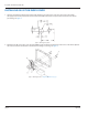
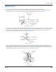
Recordall®, Gas Transmitter (Gas-RT) INSTALLING GAS-RT ON INDEX COVER 1. Using the transmitter mounting hole pattern and matching your index cover, locate the correct hole centers with the appropriate transfer punch. Drill each hole with the Vari-Bit and remove all chips and burrs from the holes before proceeding. See Figure 2 Figure 2: Mounting hole pattern 2. Mount the Gas-RT on the index cover using the TORX screws provided and reinstall the index cover on the meter.
Installation Manual WIRING GAS-RT 1. Feed the two-conductor shielded transmitter wires (Belden 9802) through the hole in the housing. 2. Strip approximately 1-1/2 inch of outer insulation sheath from the cable using the 59989-001 Coax Stripping Tool. Use caution removing the outer sheath so that the inner signal wire insulation is not damaged. See Figure 4.
Recordall®, Gas Transmitter (Gas-RT) 6. Test the entire installation including the Gas-RT and remote unit in accordance with the manufacturer's instructions. 7. Carefully fold the wires and splices to fit and then slide the Gas-RT cover into place until it snaps. NNOTE: The cover is designed for tamper protection and cannot be removed without damage. To remove the cover, press the blade of a screwdriver into the indention in the cover; doing so releases the hatch.
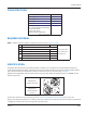
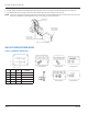
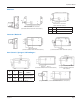
Installation Manual American® American iron case meter (index drive dial rotation) American aluminum case meter (counterclockwise index drive dial rotation) X Y Description 2312 .265 10B-Counterclockwise 2.062 .265 5B-Metric counterclockwise Lancaster®/National® National/Superior (counterclockwise index drive dial rotation) Lancaster (counterclockwise index drive dial rotation) Itron®/Actaris®/Sprague®/Schlumberger® Sprague — 1000 S.I.
Making Water Visible® MAKING WATER VISIBLE and ORION are registered trademarks of Badger Meter, Inc. Other trademarks appearing in this document are the property of their respective entities. Due to continuous research, product improvements and enhancements, Badger Meter reserves the right to change product or system specifications without notice, except to the extent an outstanding contractual obligation exists. © 2014 Badger Meter, Inc. All rights reserved. www.badgermeter.