
Specifications


Fan Coil Thermostat Controller
Specification and Installation Instructions
www.neptronic.com Page | 3
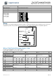
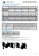
Wiring - 4 Pipe Terminal Description Details - 4 Pipe
For 4 pipe signal configuration, refer to step 15 and 18 on page 6.
For fan output configuration, refer to step 33 on page 8.
Terminals
Cool: Analog
Heat: Analog
Cool: On/Off
Heat: On/Off
Cool: Analog
Heat: On/Off or Pulse
Cool: On/Off
Heat: Analog
Step
1
Common
Common
Common
Common
Common
-
2
24 Vac
24 Vac
24 Vac
24 Vac
24 Vac
-
3
TRIAC Input Voltage (ext.)
24 Vac (ext.): if JP1 is set to external
24 Vac (ext.): if JP1 is set to external
24 Vac (ext.): if JP1 is set to external
24 Vac (ext.): if JP1 is set to external
-
4
TRIAC Output 1 (TO1)
-
4 pipe cool (on/off)
-
4 pipe cool (on/off)
9
5
TRIAC Output 2 (TO2)
-
4 pipe heat (on/off or pulse)
4 pipe heat (on/off or pulse)
-
9
6
TRIAC Output 3 (TO3)
Local reheat *
Local reheat *
Local reheat *
Local reheat *
21
Fan
1
speed
2
speed
3
speed
Analog 1
speed
2
speed
3
speed
Analog 1
speed
2
speed
3
speed
Analog 1
speed
2
speed
3
speed
Analog
7
DO Input Voltage (ext.)
24 Vac (ext.): if JP2 is set to external
24 Vac (ext.): if JP2 is set to external
24 Vac (ext.): if JP2 is set to external
24 Vac (ext.): if JP2 is set to external
8
Digital Output 1 (DO1)
-
-
High
-
-
-
High
-
-
-
High
-
-
-
High
-
33
9
Digital Output 2 (DO2)
-
High
Med
-
-
High
Med
-
-
High
Med
-
-
High
Med
-
33
10
Digital Output 3 (DO3)
Low
Low
Low
AO4
Low
Low
Low
AO4
Low
Low
Low
AO4
Low
Low
Low
AO4
33
11
Digital Input 1 (DI1)
Occupancy Sensor *
Occupancy Sensor *
Occupancy Sensor *
Occupancy Sensor *
12
Analog Input (AI1)
External Temp Sensor *
External Temp Sensor *
External Temp Sensor *
External Temp Sensor *
-
13
Analog Input (AI2)
-
-
-
-
13
14
Analog Output 1 (AO1)
4 pipe cool (analog)
-
4 pipe cool (analog)
-
18
15
Analog Output 2 (AO2)
4 pipe heat (analog)
-
-
4 pipe heat (analog)
15
16
Analog Output 3 (AO3)
Local reheat (analog)*
Local reheat (analog)*
Local reheat (analog)*
Local reheat (analog)*
21
17
A+
BACnet communication
BACnet communication
BACnet communication
BACnet communication
-
18
B-
BACnet communication
BACnet communication
BACnet communication
BACnet communication
-
* optional
Jumpers
Jumpers
Description
JP1
TRIAC Output Signal
Selector
A&B = Internal: All TRIAC output signals are linked to internal 24 Vac (same as thermostat).
B&C = External: All TRIAC output signals are linked to external 24 Vac (different than thermostat).
JP2
Digital Output Signal
Selector
A&B = Internal: All digital output signals are linked to internal 24 Vac (same as thermostat).
B&C = External: All digital output signals is linked to external 24 Vac (different than thermostat).
JP3
Mode Selection
A&B = RUN: Thermostat is in Operation Mode. (See Operation Mode Operation Modepage 13)
B&C = PGM: Thermostat is in Programming Mode. (See Programming Mode, page 4)
JP4
Fan Output Signal Selection A&B: Pin 10 of TB1 is set to digital output signal (DO3). (See Step 33)
B&C: Pin 10 of TB1 is set to analog output signal (AO4). (See Step 33)
BACnet Dip Switch (DS1)
DIP Switches
ON
OFF
1
Not Used
-
-
2
End of Line
120 ohms
None
3
Not used - -
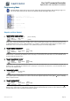
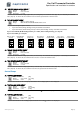
Mounting Instructions
CAUTION: Remove power to avoid a risk of malfunction.
A. Remove the captive screw that’s holding the base and the front cover of the unit together.
B. Lift the front cover of the unit to separate it from the base.
C. Pull all wires through the holes in the base.
D. Secure the base to the wall using wall anchors and screws (supplied). Make the appropriate connections.
E. Mount the control module on the base and secure using the screw.
A
E
D
C
B