
Specifications


Fan Coil Thermostat Controller
Specification and Installation Instructions
www.neptronic.com Page | 2
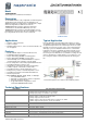
Description
Fan Coil Thermostat Controller
Operating temperature
0ºC to 50ºC [32ºF to 122ºF]
Storage temperature
-30ºC to 50ºC [-22ºF to 122ºF]
Relative Humidity
5 to 95% RH non condensing
Degree of protection of housing
IP 30 (EN 60529)
Weight
160 g. [0.36 lb]
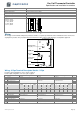
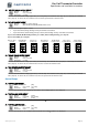
Dimensions
A = 2.85” | 73mm
B = 4.85” | 123mm
C = 1.00” | 24mm
D = 2.36” | 60mm
E = 3.27” | 83mm
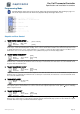
Wiring
We strongly recommend that all Neptronic products be wired to a separate grounded transformer and that transformer shall service
only Neptronic products. This precaution will prevent interference with, and/or possible damage to incompatible equipment.
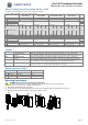
Wiring - 2 Pipe Terminal Description Details - 2 Pipe
For 2 pipe signal configuration, refer to step 9 on page 5.
For fan output configuration, refer to step 33 on page 8.
Terminals
Analog
On/Off
Floating
Step
1
Common
Common
Common
Common
-
2
24 Vac
24 Vac
24 Vac
24 Vac
-
3
TRIAC Input Voltage (ext.)
24 Vac (ext.): if JP1 is set to external
24 Vac (ext.): if JP1 is set to external
24 Vac (ext.): if JP1 is set to external
-
4
TRIAC Output 1 (TO1)
-
2 pipe on/off
2 pipe floating (close)
9
5
TRIAC Output 2 (TO2)
-
-
2 pipe floating (open)
9
6
TRIAC Output 3 (TO3)
Local reheat *
Local reheat *
Local reheat *
21
Fan
1 speed 2
speed
3
speed
Analog 1
speed
2
speed
3
speed
Analog 1
speed
2
speed
3
speed
Analog
7
DO Input Voltage (ext.)
24 Vac (ext.): if JP2 is set to external
24 Vac (ext.): if JP2 is set to external
24 Vac (ext.): if JP2 is set to external
8
Digital Output 1 (DO1)
-
-
High
-
-
-
High
-
-
-
High
-
33
9
Digital Output 2 (DO2)
-
High
Med
-
-
High
Med
-
-
High
Med
-
33
10
Digital Output 3 (DO3)
Low
Low
Low
AO4
Low
Low
Low
AO4
Low
Low
Low
AO4
33
11
Digital Input 1 (DI1)
Occupancy Sensor *
Occupancy Sensor *
Occupancy Sensor *
12
Analog Input (AI1)
External Temp Sensor *
External Temp Sensor *
External Temp Sensor *
38
13
Analog Input (AI2)
External Changeover *
External Changeover *
External Changeover *
13
14
Analog Output 1 (AO1)
2 pipe analog
-
-
9
15
Analog Output 2 (AO2)
-
-
-
9
16
Analog Output 3 (AO3)
Local reheat *
Local reheat *
Local reheat *
21
17
A+
BACnet communication
BACnet communication
BACnet communication
-
18
B-
BACnet communication
BACnet communication
BACnet communication
-
* optional
A
B
C
D
E
ºF / º C
TB1
1 2 3 4 5 6 7 8 9 10 11 12 13 14 15 16 17 18
JP3
PGM RUN
ON
1 2 3
JP1
JP4
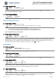
Triac Output Signal Selector
(JP1)
Mode Selector
(JP3)
Temperature Sensor
Dip Switch
Connecting Strip
(TB1)
Fan Output Signal
Selector (JP4)
Digital Output Signal
Selector (JP2)
JP2
A
B
C
C
B
A
A
B
C
A
B
C