
Specifications


6
Of course, the gain stability of this circuit is highly dependent on the resistance stability of the
feedback resistor. Fluctuations of its value due to temperature changes could cause gain errors
during observations, which are especially objectionable when all-sky photometry is done. The
special resistor used has a temperature coefficient of 200 ppm/°C which is extremely low for a
resistor of its size and
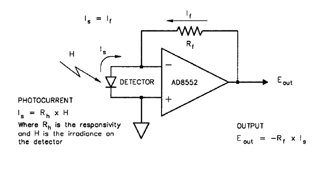
Figure 2-2. Detector/Electrometer Circuit
rating. Thus, a 20°C drop in temperature during the night, which is not uncommon, would cause
a 0.004 magnitude error in electrometer gain. Even though this error source can be safely
ignored, temperature effects on the responsivity of the detector and passbands of the filters also
have to be considered when extreme temperature changes do occur.
At the center of the H band (1650nm), the detector responsivity is close to 1 A/W (amp/watt) of
incident power. Thus, the output voltage from the preamp is equal to
E
out
= P * 1x10
9
V/W
where P is the incident power on the detector in watts. Of course, the maximum output from the
electrometer is limited to its power supply rail of about 2.7 volts.
Since extremely small currents are amplified, surface leakage currents may affect the overall
accuracy of the detector/electrometer circuit. To protect against this, the finished circuit is baked
at an elevated temperature in a vacuum dessicator for several days before it is heavily coated with
a silicon sealant that has a very high bulk resistance. During the cure time, which also may last
several days, the finished circuit is stored in a vacuum dessicator until mounted in the SSP-4.
2.4 SIGNAL PROCESSING
The voltage signal from the electrometer amplifier is processed by the voltage-to-frequency
converter to a frequency that is directly proportional to the input voltage. It is extremely