
User`s manual


Wiring Installation
MELSEC System Q, Hardware 9 – 23
Connecting to the power supply module
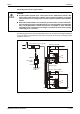
The following figure shows the wiring example of lines such as power lines and grounding lines
to the main base unit and extension base units. Please refer to the notes for wiring the power
supplies in section 7.4.
E
CAUTION:
● Use the thickest possible (max. 2 mm
2
) wires for the 110/230 V AC and 24 V DC
power cables. Twist these wires starting at the connection terminals. To prevent
short-circuit due to loosening screws, use the solderless terminals with insulation
sleeves.
● When LG and FG terminals are connected, ground the wires. Connect both termi-
nals only with ground. If LG and FG terminals are connected without grounding the
wires, the programmable controller may become susceptible to noise. Since the
LG terminal is not isolated there is the danger of an electrical shock, when touching
conducting parts or surfaces.
QH00051C
Fig. 9-22: Single power supply system wiring example
CPU
I/O
Grounding
24 V DC power
supply of I/O
modules
Extension base unit Q68B
Transformator, refer to section 9.6.
Main base unit Q38B
Extension cable
FG
SG
Input (230 V AC)
FG
SG
Input (230 V AC)
Power supply
module
24 V DC
230 V AC