
User`s manual


Installation Wiring
9 – 22
Grounding
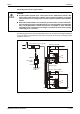
● Use a dedicated grounding wire as far as possible (see fig. 9-21, left example). Grounding
is done according class 3 (grounding resistance 100 Ω or less).
● When a dedicated grounding cannot be provided, use common grounding as shown in the
center of Fig. 9-21. Do not use the grounding as shown in the right example.
● If failures occur during operation due to grounding, cut the LG and FG terminals of the main
base unit from ground.
● For grounding a cable, use the cable of 2 mm
2
or more. Position the ground-contact point
as close as possible to the programmable controller (length of the grounding cable 30 cm
or less).
Shielding
For the communication of a MELSEC system with peripheral equipment shielded data lines
have to be used only. At best, the shielding is made of twisted copper. The density of the braiding
determines the effectiveness of the shielding. Make sure to follow the bending instructions of the
cable manufacturer, otherwise the shielding might fan out. Connect the shielding of the data line
only at one side to ground. Do not solder any wires with the shielding.
Analogue signal transmission
Use 2-wire shielded cables for low frequency analogue transmission over short distances.
Between sensor and receiver could occur potential differences on the reference conductor.
Therefore use isolating components like transformers, opto couplers etc.
Digital signal transmission
Follow the specifications of the interface concerning transfer rate and transfer distance, for an
error free digital signal transmission.
MT00063C
Fig. 9-21: Grounding procedures
PLC
Other
equipment
PLC
Other
equipment
PLC
Other
equipment