
User`s manual


Safety guidelines Installation
MELSEC System Q, Hardware 9 – 5
The power-ON procedure is as follows:
● Tur n power on .
● Set CPU to RUN.
● When DC power is established, RA2 goes ON.
● Timer (TM) times out after the DC power reaches 100 %. (The TM set value must be the
period of time from when RA2 goes ON to the establishment of 100 % DC voltage. Set this
value to approximately 0.5 seconds.) If a voltage relay is used at RA2, no timer (TM) is
required in the program.
● Turn on the start switch.
● When the magnetic contactor (MC) comes on, the output equipment is powered and may
be driven by the program.
Fail-safe measures against failure of the programmable controller
Failure of a CPU module or memory can be detected by the self-diagnosis function. However,
failure of I/O control area may not be detected by the CPU module.
In such cases, all I/O points turn on or off depending on a condition of problem, and normal oper-
ating conditions and operating safety cannot be maintained.
Though Mitsubishi programmable controllers are manufactured under strict quality control, they
may cause failure or abnormal operations due to unspecific reasons.
To prevent the abnormal operation of the whole system, machine breakdown, and accidents, the
fail-safe circuitry against failure of the programmable controller can be constructed as shown in
the following figure.
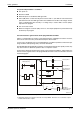
Y00 will be switched on and off in intervals of 0.5 s by SM412. Therefore use a contactless output
module with transistor outputs.
QH00041C_UK
Fig. 9-3: Fail-safe circuit example
SM412 (Q-CPU)
MC
T1
T2
Y00
Y00
0.5 s 0.5 s
Y01
Y0F
24 V
24 V DC
T1
T2
+
0 V
Y00
On delay timer
Off delay timer
CPU module
Internal program
Output module
1 s
The outputs are
switched on by
MC.
1 s
MC will be
switched on, when
Y00 is faultless.
MC