
User`s manual


I/O Number assignment Base units
MELSEC System Q, Hardware 8 – 13
8.4 I/O Number assignment
A CPU of the MELSEC System Q automatically recognises the slots available in main and exten-
sion base units and assigns addresses to the inputs and outputs accordingly.
The assignment can also be done by the user. Thus slots can be left empty or addresses can be
reserved for future extensions.
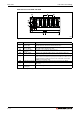
The following figure shows examples for I/O assignment:
QH00053C
Fig. 8-10: I/O number assignment example
X/Y
0
0
14
22
6
13
21
5
15
23
7
16
24
8
17
25
9
18
10
19
11
20
12
1234
A0
1A0
2A0
20
C0
1C0
2C0
40
E0
1E0
2E0
60
100
200
300
80
120
220
320
140
240
160
260
180
280
X/Y
X/Y
X/Y
X/Y
X/Y
X/Y
X/Y
X/Y
X/Y
X/Y
X/Y
X/Y
X/Y
X/Y
X/Y
X/Y
X/Y
X/Y
X/Y
X/Y
X/Y
X/Y
X/Y
X/Y
X/Y
O
U
T
O
U
T
I
N
I
N
O
U
T
I
N
O
U
T
X/Y
0
0
14
22
6
13121110
21
54
15
23
7
16
24
8
17
25 26 27
9
18 19 20
123
A0
1A0180160140
2A0
20
C0
1C0
2C0
40
E0
1E0
2E0
60
100
200
300
120
220
320 340 360
80
240 260 280
X/Y
X/Y
X/Y
X/Y
X/Y
X/Y
X/Y
X/Y
X/Y
X/Y
X/Y
X/Y
X/Y
X/Y
X/Y
X/Y
X/Y
X/Y X/Y X/Y X/Y X/Y X/Y
X/Y
X/Y X/Y X/Y
O
U
T
O
U
T
I
N
I
N
O
U
T
I
N
O
U
T
Auto mode
Detail mode
C
P
U
C
P
U
Vacant
Extension stage 3:
Extension base unit Q65B
10 user specific slots
Extension stage 2:
Extension base unit Q68B
8 user specific slots
Extension stage 1:
Extension base unit Q68B
6 user specific slots
Main base unit Q35B
4 user specific slots
Extension stage 1
Extension stage 2
Extension stage 3
The addresses of slots 23 to 27 are reserved
for future extensions.
Power supply
module
Power su pply
module
Pow er su pp ly
module
Power su pply
module
Power supply
module
Power su pp ly
module
Power su pply
module
Pow er su pp ly
module
Vacant
Vacant