
User`s manual


Base units Part names and settings
8 – 6
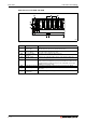
Extension base units Q52B and Q55B
Q55B
Fig. 8-3: Part names of extension base units Q52B and Q55B
No. Name Application
Extension cable
connector (IN)
Connector for connecting an extension cable (IN) (for signal communications
with the main base unit or other extension base unit)
Extension cable
connector (OUT)
Connector for connecting an extension cable (OUT) (for signal communica-
tions with another extension base unit).
Base cover of cable
connectors
Protective cover of extension cable connector.
Stage No. setting
connector
Connector for setting the number of bases of the extension base unit.
7 extension stages can be set.
Module connector Connectors for installing the I/O modules and intelligent function modules.
To the connectors located in the spare space where these modules are not
installed, attach the supplied connector cover or the blank cover module
(QG60) to prevent entry of dirt.
Module fixing screw hole Screw hole for fixing the module to the base unit. Screw size: M3x12
Base mounting hole Hole for mounting this base unit onto the panel such as a control panel (for
M4 screw)
DIN rail adapter
mounting hole
Hole for mounting DIN rail adapter.
Tab. 8-5: Description for part names of extension base units Q52B and Q55B
IN OUT