
User`s manual


4
I/O NUMBER ASSIGNMENT
4.2 Concept of I/O Number Assignment
4.2.1 I/O numbers of base unit
4 - 2
1
Overview
2
Performance
Specification
3
Sequence Program
Configuration and
Execution Conditions
4
I/O Nunber Assignment
5
Memories and Files
Handled by CPU Module
6
Functions
7
Communication with
Intelligent Function
Module
8
Parameters
4.2 Concept of I/O Number Assignment
4.2.1 I/O numbers of base unit
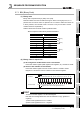
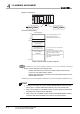
At power-on or reset cancel, the CPU module assigns I/O numbers.
I/O numbers are assigned automatically from the right side of the CPU module of the main
base unit.
When two CC-Link Safety master modules and one MELSECNET/H module are mounted
on the main base unit, the I/O numbers are as shown in Diagram 4.1
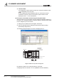
If the base unit has empty slots mounted with no CC-Link Safety master modules or no
MELSECNET/H module are mounted, the points designated at the "I/O assigment" tab
screen in the "(PLC) Parameter" dialog box are assigned to the empty slots. (Default
value is 16 points.)
Remark
The head I/O can be changed for each slot with the GX Developer I/O assignment.
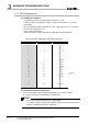
4.2.2 I/O number of remote station
In the CC-Link Safety system, CPU module input (X) and output (Y) can be assigned to
remote station I/O modules and controlled.
(1) CPU module I/O numbers that can be used at remote stations
When two CC-Link Safety master modules and one MELSECNET/H module are mounted
on the main base unit, X/Y0 - X/Y5F are used.
When using CPU module input (X) and output (Y) for remote station I/O numbers, use X/
Y60 or later.
Diagram 4.1 I/O number assignment example
I/O point
I/O number
Slot number
CPU 0 1 2 3
32 32 32
Base unit
CC-Link Safety
master module
CC-Link Safety
master module
MELSECNET/H
module
00
H
1F
H
20
H
3F
H
40
H
5F
H