
Instruction manual

Basic Electrostatics System Model No. ES-9080
24
®
4. Observe how the potential difference reading from the electrometer
varies as more charge is put in the capacitor.
5. Double the plate separation and repeat the experience. What
happens to the potential now? Compare the values to the previous
case.
3B.2: Q Measured, C Variable, V Constant
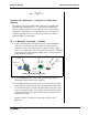
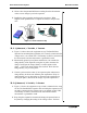
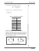
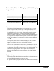
1. Figure 3.3 above shows the equipment set up. The Parallel Plate
capacitor has an initial plate separation of 6 cm and is connected to the
voltage source, set at 2000 VDC. The Faraday Ice Pail is connected to
the electrometer, and the electrometer is grounded to earth.
2. Momentarily ground a proof plane and then use it to examine the
charge density of the capacitor, using the ice pail to measure the
charge. Investigate the charge density at various points on the
plates — both on the inner and the outer surfaces. How does the
charge density vary over the plate?
3. Choose a point near the center of one capacitor plate and measure
charge density in this area at different plate separations. (Keep in
mind whether you are increasing or decreasing the capacitance by
moving the plates.) How does the charge vary with capacitance?
3B.3 Q Measured, V Variable, C Constant
1. Figure 3.3 shows the equipment set up, which is identical to the setup
for B2. The Parallel Plate capacitor has an initial plate separation of 6
cm and is connected to the voltage source, set initially at 3000 VDC.
The Faraday Ice Pail is connected to the electrometer and the
electrometer is grounded to earth.
2. Keep the plate separation constant and change the potential across
the plates by changing the setting of the voltage source. You have
red lead
black lead
d
2000 V
Figure 3.3: Demonstration Setup