Instruction Manual Manual No. 012-07227D Basic Electrostatics System Model No.
Basic Electrostatics System Model No. ES-9080A Table of Contents Equipment List........................................................... 3 Introduction .......................................................... 4-5 Equipment Description .............................................. 5-11 Electrometer ...................................................................................................................................5 Electrostatics Voltage Source ...........................................
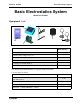
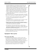
Model No. ES-9080 Basic Electrostatics System Basic Electrostatics System Model No. ES-9080 Equipment List 2 4 5 6 6 1 3 Included Equipment Replacement Model Number* 1. Basic Electrometer (1)** ES-9078 2. Electrostatics Voltage Source (1)** ES-9077 3. Basic Variable Capacitor (1)** ES-9079 4. Charge Producers (2) and proof plane (1) ES-9075B 5. Faraday Ice Pail and Shield (1) ES-9042A 6. Conductive Spheres (2) ES-9059B *Use Replacement Model Numbers to expedite replacement orders.
Basic Electrostatics System Model No. ES-9080 Introduction Demonstrations of electrostatic phenomenon have traditionally been limited to the simplest experiments, using the most elementary equipment, because of problems with technique and apparatus. Moreover, the traditional demonstrations usually gave qualitative rather than quantitative results. PASCO has attempted to remedy this by designing the complete ES-9079 Basic Electrostatics system.
Model No. ES-9080 Basic Electrostatics System particularly humid day can cause charges to leak off any of the apparatus, radically changing the charge distribution. To help minimize leakage, keep all equipment free of dust and oil (e.g. from fingerprints). On the other hand, a particularly dry day can cause charge to easily build up in any moving object, including people. Minimize all movement when demonstrating on a very dry day.
Basic Electrostatics System Model No. ES-9080 With these features, you’ll find that your electrostatics demonstrations and labs are easier to perform and, with quantitative data, are more informative.
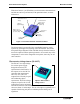
Model No. ES-9080 Basic Electrostatics System Variable Capacitor (ES-9079) The PASCO experimental variable capacitor consists of two metal plates, 20 cm in diameter, which can be adjusted to various separations. The movable plate is mounted on a calibrated slide which gives the plate separation directly in centimeters. Binding posts are provided for electrical connection to each plate.
Basic Electrostatics System Model No. ES-9080 Here are some guidelines in the proper use and care of the charge producers that are important to remember: • If a zero charge is desirable, discharge the charge producers by touching the conductive disk to ground. To be sure the disk is fully discharged, gently breathe on the non-conductive neck. The moisture from your breath will help remove any stray charge. • Avoid touching the neck during normal use.
Model No. ES-9080 Basic Electrostatics System By touching the proof plane to a surface, the proof plane will acquire the same charge distribution as the section of the surface it touched (See Figure 6). By measuring the charge on the proof plane, the charge density on that part of the surface can be determined. The greater the charge on the proof plane, the greater the charge density on the surface where the proof plane made contact.
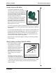
Basic Electrostatics System Model No. ES-9080 Faraday Ice Pail (ES-9042A) The PASCO Faraday Ice Pail is shown in Figure 8. Originally designed by Michael Faraday, it works on the principle that any charge placed inside a conducting surface will induce an equal charge on the outside of the surface. It is an excellent product for sampling charges and charge distributions. The PASCO version illustrated above consists of two wire mesh cylinders, one inside the other, mounted on a molded plastic bottom.
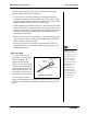
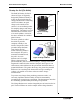
Model No. ES-9080 Basic Electrostatics System Conductive Spheres (ES-9059B) The conductive spheres are used to store electrical charge. The PASCO Model ES-9059B spheres are composed of plastic resin mold plated with a copper base, outer plating of non-sulphur brite nickel, with final plating of chrome. The spheres are mounted on insulting polycarbonate rods, attached to a support base.
Basic Electrostatics System Model No. ES-9080 Five binding posts allow the voltage source and/or the electrometer to be connected to components. Electrometer Operation and Setup Requirements The controls on the front panel of the electrometer are explained in Figure 1. Whether you are using the electrometer to measure voltage, current or charge, the setup procedure should be followed each time you turn on the electrometer.
Model No. ES-9080 Basic Electrostatics System deflection (e.g., a setting of 30 means that a full-scale meter deflection indicates a voltage of 30 volts). Important Points for General Operation: 1. Between measurements, always press the Zero button to discharge all current from the electrometer. 2. Shorting the test leads together is insufficient. There may still be stray charges within the electrometer circuitry. 3.
Basic Electrostatics System Model No. ES-9080 Demonstration 1: Faraday Ice Pail and Charge Production Equipment Required: Electrometer (ES-9078) Faraday Ice Pail (ES-9042A) Charge Producers (ES-9057B) Test Leads Earth ground connection Proof plane (optional) Suggestions for Introducing the Experiment Start by showing that the electrometer is directly measuring potential difference by connecting a battery to it and measuring its voltage.
Basic Electrostatics System Model No. ES-9080 compared to charging it by induction, and to demonstrate the conservation of charge. Before beginning any experiment using the ice pail, the pail must be momentarily grounded. When the ice pail is connected to the electrometer, and the electrometer is connected to an earth-ground, simply press the ZERO button whenever you need to discharge both the pail and the electrometer.
Basic Electrostatics System Model No. ES-9080 • Always remove any stray charge on the necks and handles of the charge producers by touching the necks and handles to the grounded shield. You must also be grounded while doing this. It also helps if you breathe on the neck of the charge producer, so that the moisture in your breath removes any residual charge on the neck. • Rub the white and blue surfaces together to separate charges. • Keep in your hand only the producer you are going to use.
Model No. ES-9080 Basic Electrostatics System from touching anything else after charging. (Keep them in your hands, without letting them touch each other or the ice pail.) 2. Use the Faraday Ice Pail to measure the magnitude and polarity of each of the charged wands by inserting them one at a time into the ice pail and noting the reading on the electrometer.
Basic Electrostatics System Model No.
Model No. ES-9080 Basic Electrostatics System the ice pail), the charge on the surface is not depleted. That charge which the proof plane removed for one measurement is always returned to the surface when the next sampling is made. NOTE: When the disk of the proof plane touches the surface being sampled, it essentially becomes part of the surface. To minimize distortion of the surface shape when sampling, hold the proof plane flat against the surface, as indicated in the accessory instructions.
Basic Electrostatics System Model No. ES-9080 Analysis 1. What produced the charge distributions at each step of the experiment? 2. Why did any charge remain on the second sphere even after it was grounded? Extra Things to Try 1. To show that the charge on a conductor always resides on the outside surface, bend a flexible sheet of metal into a cylinder. Charge the cylinder and measure the charge density in the inner and outer surfaces. Notice that charge is always on the outside. 2.
Model No. ES-9080 Basic Electrostatics System Demonstration 3: Capacitance and Dielectrics Equipment Required: Electrometer (ES-9078) Faraday Ice Pail (ES-9042A)l Charge Producers (ES-9057B) Proof Planes (ES-9057B) Electrostatic Voltage Source (ES-9077) Test leads 13 cm Conductive Spheres (2) (ES-9059B) Variable Capacitor (Parallel Plates) (ES-9079) Capacitor (about 30 pF) (ES-9043) Sheet of dielectric material (See Table 3.
Basic Electrostatics System Model No. ES-9080 CE need not be considered. This is not true, however, when using the Basic Variable Capacitor (ES-9079). CE Cext Capacitance of object connects to the Electrometer Voltmeter Internal capacitance = 25 pF, without cable Figure 3.1: Ideal Schematic of the Electrometer Procedure 3A: Measuring the Electrometer’s Capacitance Use this procedure to measure a precise value of the capacitance provided by the electrometer and all cables connected to it.
Model No. ES-9080 Basic Electrostatics System ( V – VE ) CE = ---------------------- ⋅ C V Procedure 3B: Measuring C, V and Q for a Parallel Plate Capacitor The purpose of the experiments listed in this part is to qualitatively study the relationship between C, V, and Q for the parallel plate capacitor. Values read by the electrometer are to be used as relative, comparative measurements.
Basic Electrostatics System Model No. ES-9080 4. Observe how the potential difference reading from the electrometer varies as more charge is put in the capacitor. 5. Double the plate separation and repeat the experience. What happens to the potential now? Compare the values to the previous case. black lead d red lead 2000 V Figure 3.3: Demonstration Setup 3B.2: Q Measured, C Variable, V Constant 1. Figure 3.3 above shows the equipment set up.
Model No. ES-9080 Basic Electrostatics System to move the connecting cable from the 3000 V to the 2000 V slot. Examine the charge density near the center of one capacitor plate. How does the charge vary with the voltage? Repeat with 1000 VDC. 3B.4: V Measured, C Variable, Q Constant 1. Figure 3.4 shows the equipment set up. The Parallel Plate capacitor is connected to the electrometer and the electrometer is Figure 3.4: Demonstration Setup grounded to earth.
Basic Electrostatics System Model No. ES-9080 NOTE: Depending on the model of parallel plate capacitor you have, there may be only one plate that is movable. If your model allows both plates to be moved, choose one to keep fixed and the other to be the movable one. 1. Connect the electrometer across the plates of the capacitor and set the separation between the plates to about 3 mm. 2. Raise the side of the set up nearest the movable plate by setting a block about 3 cm high below it, as shown in Figure 3.
Model No. ES-9080 Basic Electrostatics System Analysis: The calculations needed to determine the dielectric constant are long, but straight forward: CE , qE before CE , qE CP qP CP qP VO VO after Figure 3.6: Circuit diagrams with and without the dielectric Before inserting the dielectric... Let q p be the charge on the capacitor plates, and C p be the capacitance of the plates, without the dielectric. Let q E be the charge on CE, the internal capacitance of the electrometer.
Basic Electrostatics System Model No. ES-9080 After some algebra and rearranging, you find that CE ( Vi –Vf ) + Cp V C ′p ------- = --------------------------------------------i Cp Cp Vf where the ratio ( C ′p ⁄ Cp ) is the dielectric coefficient κ : ε Ad C′ κ = ----------= -------p Cp εO Ad Table 3.1: Some Dielectric Coefficients κ Material Vacuum 1 Air 1.00059 Polystyrene 2.6 Paper 3.7 Pyrex 4.7 Mica 5.4 Porcelain 6.
Model No. ES-9080 Basic Electrostatics System 3D.1: Capacitors in Series Make sure all capacitors are uncharged before connecting them. (Use a short wire to momentarily short each one.) 1. Set up the series circuit, as shown in Figure 3.7a. 2. Plug in to the 30 VDC output on the Voltage Source. Close switch A to charge capacitor C1. 3. Using the known value of C1, calculate the initial amount of charge on C1. Let’s call it Qo. (Remember Q=CV.) 4. Throw the switch to position B.
Basic Electrostatics System Model No.
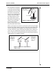
Model No. ES-9080 Basic Electrostatics System 2. Set up the circuit shown in Figure 4.1, where the resistor and the capacitor are connected in series to the voltage source, set at 30 VDC. The electrometer output goes to one of the analog channels of ScienceWorkshop. Use a single-pole double-throw switch. signal output red lead double-throw switch electrometer interface signal black lead Figure 4.1: Experimental Setup and Circuit 3. Set up your experiment display in the computer to plot voltage vs.
Basic Electrostatics System Model No. ES-9080 1. Calculate 63% of the voltage of the source. Locate the position in the graph where the voltage has reached this value. How long a time has passed to reach 63% of the voltage of the source? This time is RC. (Using the Smart Tool in Data Studio or the Smart Cursor Tool in ScienceWorkshop makes these measurements easy!) 2. Compare the measured time constant from the graph with the calculated from the known values of and R.
Model No. ES-9080 Basic Electrostatics System - ln0.01], where Vo is the voltage of the source. Choose a signal such that the period of the wave is at least double this charging time. analog channel interface computer electrometer Figure 4.3: Experimental Setup Experimental Setup 1. Set up the circuit shown in Figure 4.3, where the resistor and the capacitor are connected in series to the signal output generator of the ScienceWorkshop interface. Use a 200µF capacitor and a resistance of 1000 Ω.
Basic Electrostatics System Model No. ES-9080 Extra Things to Try: 1. Check what is happening to the voltage across the resistor while the capacitor charges and discharges.
Model No. ES-9080 Appendix A: Information Basic Electrostatics System Copyright and Warranty Copyright Notice The PASCO scientific 012-7227C Electrostatics Manual is copyrighted and all rights reserved. However, permission is granted to non-profit educational institutions for reproduction of any part of the 012-7227C Electrostatics Manual, providing the reproductions are used only for their laboratories and are not sold for profit.
Basic Electrostatics System Model No. ES-9080 Appendix B: Technical Support For assistance with the Basic Electrostatics Systems equipment or any other PASCO products, contact PASCO as follows: Address: PASCO scientific 10101 Foothills Blvd. Roseville, CA 95747-7100 Phone: (916) 786-3800 36 FAX: (916) 786-3292 Web: www.pasco.com Email: techsupp@pasco.