
User`s guide

Imaging Modalities
2D/BMode Imaging
Revision D.0 7-41
ssn February 10, 1999 C:\WINNT\Profiles\dapowell\Desktop\D.0 Books\CD FILES SONOS
D.0\System Basics D.0\Frame Files\7CH.FM add.2
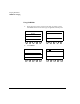
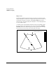
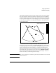
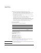
The following illustration shows the biopsy needle graphic. The diverging dotted
lines show the area in which the needle can be expected to travel. These display
guidelines should be used as an indicator only. Needle deflection or bending may
occur as it passes through tissue. Use the imaging screen to monitor the progress
of the needle. The spacing is 1 cm along the needle path for deep depths and 0.5
cm for shallow depths.
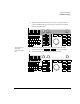
The dotted lines are set at an angle to the image. When the needle can be
mounted in more than one position, the Crossover Depth rotary control selects
the display appropriate for the needle position. The display changes to show the
angle corresponding to the selected position. A crosshair cursor between the
dotted lines indicates the target. The trackball controls the cursor location on the
ideal needle path. In the upper right corner of the screen, NEEDLE LENGTH
indicates the minimum length of needle required to reach the target. This is the
distance from the top of the needle guide to the target.
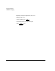
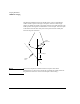
CAUTION The onscreen guidelines are intended as guides only and should never be used as
absolute references.
NEEDLE LENGTH=8.0 CM